


AP-7131N-FGR Access Point Product Reference Guide
2-18
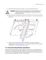
The Power Injector receives power as soon as AC power is applied. For more information
on using the Power Injector, see
Power Injector System on page 2-7
.
For standard 48-Volt Power Adapter (Part No. 50-14000-247R) and line cord installations:
a. Connect a RJ-45 CAT5e (or CAT6) Ethernet cable between the network data supply (host)
and the access point’s GE1/POE port.
b. Verify the power adapter is correctly rated according the country of operation.
c. Connect the power supply line cord to the power adapter.
d. Attach the power adapter cable into the power connector on the access point.
e. Plug the power adapter into an outlet.
15. Verify the behavior of the LEDs. For more information, see
LED Indicators on page 2-18
.
16. Place the ceiling tile back in its frame and verify it is secure.
The access point is ready to configure. For information on an access point default
configuration, see
Getting Started on page 3-1
. For specific details on system
configurations, see
System Configuration on page 4-1
.
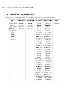
2.8 LED Indicators
An AP-7131N-FGR model access point has six LEDs on the top of the access point housing, and one
optional LED light pipe at the bottom of the unit. However, an AP-7131N-FGR model access point does
not use LED 6, as no third radio is available. Five LEDs illuminate (on top of the housing) for dual radios
models.
The access point utilizes two (different colored) lights below each LED. Only one light displays within
a LED at any given time. Every light within each LED is exercised during startup to allow the user to
see if an LED is non-functional. The LEDs turn on and off while rotating around in a circle. Since two
LEDs feed each light pipe, the pattern is from left to right, then right to left.
NOTE
LED blink rate is proportional to activity. The busiest traffic corresponds
to the fastest blink, while the slowest traffic corresponds to slowest
blink.
Summary of Contents for AP-7131N-FGR
Page 1: ...AP 7131N FGR Access Point Product Reference Guide ...
Page 3: ...AP 7131N FGR Access Point Product Reference Guide 72E 126727 01 Revision A September 2009 ...
Page 4: ......
Page 55: ...Hardware Installation 2 11 ...
Page 68: ...AP 7131N FGR Access Point Product Reference Guide 2 24 ...
Page 90: ...AP 7131N FGR Access Point Product Reference Guide 3 22 ...
Page 148: ...AP 7131N FGR Access Point Product Reference Guide 4 58 ...
Page 300: ...AP 7131N FGR Access Point Product Reference Guide 6 72 ...
Page 338: ...AP 7131N FGR Access Point Product Reference Guide 7 38 ...
Page 635: ...Configuring Mesh Networking 9 23 5 Define a channel of operation for the 802 11a n radio ...
Page 648: ...AP 7131N FGR Access Point Product Reference Guide 9 36 ...
Page 672: ...AP 7131N FGR Access Point Product Reference Guide 10 24 line con 0 line vty 0 24 end ...
Page 692: ...AP 7131N FGR Access Point Product Reference Guide B 14 ...
Page 698: ...AP 7131N FGR Access Point Product Reference Guide B 20 ...
Page 702: ...AP 7131N FGR Access Point Product Reference Guide C 4 ...
Page 707: ......


