


Hardware Installation
2-17
8.
Connect the light pipe to the bottom of the access point. Align the tabs and rotate
approximately 90 degrees. Do not over tighten
9.
Fit the light pipe into hole in the tile from its unfinished side.
10. Place the decal on the back of the badge and slide the badge onto the light pipe from the
finished side of the tile.
11. Attach the radio antennas to their correct connectors. For more information on available
antennas, see
Antenna Options on page 2-4
.
12. Motorola recommends attaching safety wire to the access point’s safety wire tie point or
security cable (if used) to the access point’s lock port.
13. Align the ceiling tile into its former ceiling space.
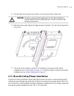
14. Cable the access point using either a Power Injector or approved line cord and power supply.
For Power Injector installations:
a. Connect a RJ-45 CAT5e (or CAT6) Ethernet cable between the network data supply (host)
and the Power Injector
Data In
connector.
b. Connect a RJ-45 CAT5e (or CAT6) Ethernet cable between the Power Injector
Data &
Power Out
connector and the access point’s GE1/POE port.
c. Ensure the cable length from the Ethernet source to the Power Injector and access point
does not exceed 100 meters (333 ft). The Power Injector has no On/Off power switch.
CAUTION
Do not supply power to the access point until the cabling of the unit is
complete.
!
Summary of Contents for AP-7131N-FGR
Page 1: ...AP 7131N FGR Access Point Product Reference Guide ...
Page 3: ...AP 7131N FGR Access Point Product Reference Guide 72E 126727 01 Revision A September 2009 ...
Page 4: ......
Page 55: ...Hardware Installation 2 11 ...
Page 68: ...AP 7131N FGR Access Point Product Reference Guide 2 24 ...
Page 90: ...AP 7131N FGR Access Point Product Reference Guide 3 22 ...
Page 148: ...AP 7131N FGR Access Point Product Reference Guide 4 58 ...
Page 300: ...AP 7131N FGR Access Point Product Reference Guide 6 72 ...
Page 338: ...AP 7131N FGR Access Point Product Reference Guide 7 38 ...
Page 635: ...Configuring Mesh Networking 9 23 5 Define a channel of operation for the 802 11a n radio ...
Page 648: ...AP 7131N FGR Access Point Product Reference Guide 9 36 ...
Page 672: ...AP 7131N FGR Access Point Product Reference Guide 10 24 line con 0 line vty 0 24 end ...
Page 692: ...AP 7131N FGR Access Point Product Reference Guide B 14 ...
Page 698: ...AP 7131N FGR Access Point Product Reference Guide B 20 ...
Page 702: ...AP 7131N FGR Access Point Product Reference Guide C 4 ...
Page 707: ......


