


Network Management
5-3
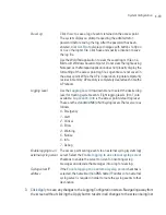
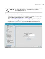
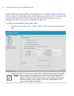
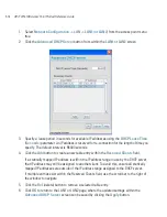
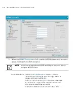
3.
Refer to the
LAN Ethernet Timeout
field to define how LAN Ethernet inactivity is
processed by the access point.
Use the
Ethernet Port Timeout
drop-down menu to define how the access point interprets
inactivity for the LAN assigned to the Ethernet port. When
Enabled
is selected, the access
point uses the value defined in the
Sec.
box (default is 30 seconds). Selecting
Disabled
allows the LAN to use the Ethernet port for an indefinite timeout period. Select the
Hardware Detect
option to use the physical LAN port to detect activity. If the LAN port
does not detect a physical connection, the radio is unavailable to the access point.
4.
Refer to the
802.1x Port Authentication
field if using port authentication over the access
point’s LAN port.
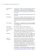
Enable
Select the LAN1 and/or LAN2 checkbox to allow the forwarding of
data traffic over the specified LAN connection. The LAN1
connection is enabled by default, but both LAN interfaces can be
enabled simultaneously. The LAN2 setting is disabled by default.
LAN Name
Use the
LAN Name
field to modify the existing LAN name. LAN1
and LAN2 are the default names assigned to the LANs until
modified by the user.
Ethernet Port
The
Ethernet Port
radio buttons allow you to select one of the two
available LANs as the LAN actively transmitting over the access
point’s LAN port. Both LANs can be active at any given time, but
only one can transmit over the access point’s physical LAN
connection, thus the selected LAN has priority.
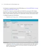
Enable 802.1q
Trunking
Select the
Enable 802.1q Trunking
checkbox to enable the LAN
to conduct VLAN tagging. If selected, click the
WLAN Mapping
button to configure mappings between individual WLANs and
LANs. If enabled, the access point is required to be connected to a
trunked port.
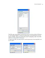
VLAN Name
Click the
VLAN Name
button to launch the
VLAN Name
screen
to create VLANs and assign them VLAN IDs. For more information,
see
Configuring VLAN Support on page 5-5
.
WLAN Mapping
Click the
WLAN Mapping
button to launch the
VLAN
Configuration
screen to map existing WLANs to one of the two
LANs and define the WLAN’s VLAN membership (up to 16
mappings are possible per access point). For more information, see
Configuring VLAN Support on page 5-5
.
Summary of Contents for AP-7131N-FGR
Page 1: ...AP 7131N FGR Access Point Product Reference Guide ...
Page 3: ...AP 7131N FGR Access Point Product Reference Guide 72E 126727 01 Revision A September 2009 ...
Page 4: ......
Page 55: ...Hardware Installation 2 11 ...
Page 68: ...AP 7131N FGR Access Point Product Reference Guide 2 24 ...
Page 90: ...AP 7131N FGR Access Point Product Reference Guide 3 22 ...
Page 148: ...AP 7131N FGR Access Point Product Reference Guide 4 58 ...
Page 300: ...AP 7131N FGR Access Point Product Reference Guide 6 72 ...
Page 338: ...AP 7131N FGR Access Point Product Reference Guide 7 38 ...
Page 635: ...Configuring Mesh Networking 9 23 5 Define a channel of operation for the 802 11a n radio ...
Page 648: ...AP 7131N FGR Access Point Product Reference Guide 9 36 ...
Page 672: ...AP 7131N FGR Access Point Product Reference Guide 10 24 line con 0 line vty 0 24 end ...
Page 692: ...AP 7131N FGR Access Point Product Reference Guide B 14 ...
Page 698: ...AP 7131N FGR Access Point Product Reference Guide B 20 ...
Page 702: ...AP 7131N FGR Access Point Product Reference Guide C 4 ...
Page 707: ......