Guide
to
Electrophysiological
Recording
is
recommended
if
this
is
the
only
intended
use).
Virtual
Ground
output
attenuation
(VG)
specifies
the
sensitivity.
The
smaller
VG
is
more
sensitive
and
it
is
used
for
low
currents.
Current
Clamp
Circuit
In
I
‐
Clamp
mode
a
separate
headstage
circuit
is
used,
called
a
voltage
follower.
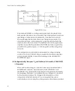
The
essential
features
of
a
voltage
follower
are
shown
in
Figure
Figure
41.
A1
is
an
(effectively)
infinite
input
resistance,
unity
‐
gain
op
amp,
the
output
of
which
is
the
pipette
voltage,
V
p
.
A2
is
a
summing
amplifier
used
for
injecting
current
into
the
cell.
The
voltage
across
the
headstage
resistor
R
0
is
equal
to
V
cmd
regardless
of
V
p
.
Thus
the
current
through
R
0
is
given
exactly
by
I
=
V
cmd
/
R
0
.
If
stray
capacitances
are
ignored,
all
of
this
current
is
injected
into
the
cell.
Figure
41.
Voltage
follower
headstage.
Note:
V
cmd
is
limited
to
12
V
in
the
Axoclamp
900A,
which
in
turn
limits
the
maximum
amount
of
current
that
can
be
injected
through
the
headstage
resistor
into
the
electrode.
For
example,
with
R
0
=
100
M
Ω
,
the
maximum
current
that
can
be
injected
is
12
V/100
M
Ω
=
120
nA.
These
current
limits
are
listed
in
Table
1,
page
74.
71


