Setup
and
Tutorials
2.
Connect
the
HS
‐
9A
×1
headstage
connector
to
the
CHANNEL
2
HEADSTAGE
INPUT
on
the
rear
panel.
3.
Connect
headstage
1
to
the
CLAMP
‐
1U
model
cell
at
the
ME
1
connector.
4.
Ground
the
CLAMP
‐
1U
case
to
the
signal
ground
socket
on
the
rear
of
the
headstage.
The
switch
should
be
in
the
BATH
position.
5.
Place
the
headstage
and
model
cell
into
a
shielded
enclosure
(optional)
ensuring
that
the
shield
is
also
connected
to
the
signal
ground.
6.
Turn
the
Axoclamp
900A
power
ON.
7.
Run
the
Axoclamp
900A
Commander
software.
8.
Press
the
Reset
to
Program
Defaults
button
in
the
toolbar
at
the
top
of
the
Commander
and
accept
the
warning.
Information
about
the
connected
headstages
is
displayed
at
the
top,
including
the
current
injection
resistance
for
each
headstage.
For
the
HS
‐
9A
×0.1
headstage,
R
0
is
100
M
Ω
,
and
for
the
HS
‐
9A
×1,
R
0
is
10
M
Ω
.
9.
In
the
I
‐
Clamp
1
tab,
with
the
CLAMP
‐
1U
switch
in
the
BATH
position,
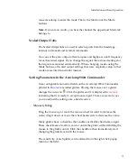
press
the
Pipette
Offset
Zero
button.
Figure
6.
Pipette
Offset
controls.
The
corrected
offset
voltage
for
the
headstage
should
be
less
than
±10
mV.
10.
The
Channel
1
SCALED
OUTPUT
Signal
selected
should
be
“Headstage
1,
Membrane
Potential
(10
mV/mV)”.
29

