Guide
to
Electrophysiological
Recording
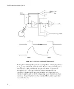
capacitor
and
buffer
amplifier
arrangement
constitute
an
analog
memory
known
as
a
sample
‐
and
‐
hold
amplifier.
Immediately
after
the
sample
period,
the
current
injection
period
begins
when
switch
S1
changes
over
from
the
zero
volts
position
to
the
current
‐
command
voltage
(V
cmd
)
position.
This
connects
V
cmd
to
a
differential
amplifier
(A4)
arranged
so
that
its
output
is
V
1
+
V
cmd
.
The
voltage
appearing
across
R
0
is
exactly
equal
to
V
cmd
thereby
forcing
the
current
(I
0
)
into
the
microelectrode
to
be
equal
to
V
cmd
/
R
0
.
Amplifiers
A4
and
A1
and
resistor
R
0
constitute
a
controlled
‐
current
source
(CCS)
which
injects
a
current
into
the
microelectrode
directly
proportional
to
the
voltage
at
the
input
of
the
CCS
irrespective
of
the
resistance
of
the
microelectrode
or
the
voltage
at
its
tip.
89


