Setup
and
Tutorials
The
Headstage
1
Membrane
Potential
passing
through
a
pre
‐
determined
level.
The
direction
it
passes
through
the
level
is
also
programmable
(negative
to
positive
or
positive
to
negative).
Going
into
V
‐
Clamp
can
be
instantaneous
(<
2
ms)
or
can
be
delayed
up
to
500
ms.
Returning
to
I
‐
Clamp
mode
can
be
programmed
to
be:
Manual
return.
On
external
MODE
BNC
input
going
low
or
high,
depending
on
how
the
logic
is
set
for
going
into
voltage
‐
clamp
mode.
After
a
programmable
time
ranging
between
2
ms
and
500
seconds.
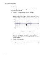
Example
of
Auto
Mode
Switching
The
following
switches
from
I
‐
Clamp
to
TEVC
mode
when
membrane
voltage
in
headstage
1
passes
through
+20
mV
in
a
negative
to
positive
direction.
It
stays
in
TEVC
mode
for
500
ms
generating
a
0
mV
to
10
mV
p-p
10
Hz
Seal
Test
waveform
and
then
returns
to
I
‐
Clamp.
The
cycle
then
repeats.
Set
up
both
I
‐
Clamp
and
V
‐
Clamp
modes
using
the
appropriate
tutorials
and
model
cell
prior
to
going
into
AUTO
mode.
This
will
prevent
oscillations
when
switching
into
a
new
mode.
Make
sure
to
uncheck
Oscillation
Detection
in
the
appropriate
V
‐
Clamp
tab
when
setting
up
the
V
‐
Clamp
mode.
To
initiate
an
I
‐
Clamp
to
V
‐
Clamp
transition,
a
waveform
in
headstage
1
that
moves
through
+20
mV
is
required.
To
do
this
we
will
use
a
TUNE
input
from
Headstage
2.
1.
In
Channels
1
&
2
select
IC
mode.
51


