Guide
to
Electrophysiological
Recording
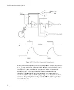
After
30%
of
one
cycle
has
elapsed,
the
voltage
‐
recording
period
begins
when
S1
changes
back
to
the
zero
volts
position.
Passive
decay
occurs
because
the
input
of
the
CCS
is
zero
volts
and
thus
its
output
current
is
zero.
Sufficient
time
must
be
allowed
during
the
voltage
‐
recording
period
for
the
voltage
to
decay
to
within
a
millivolt
or
less
of
V
m
.
At
the
end
of
the
passive
decay
period
S2
is
again
briefly
closed
and
a
new
sample
of
V
m
is
taken
to
begin
a
new
cycle.
The
actual
voltage
used
for
recording
purposes
is
the
sampled
voltage.
The
Scaled
Output
Headstage
1
Membrane
Potential
signal
is
the
sampled
membrane
potential.
The
instantaneous
current
into
the
microelectrode
is
monitored
by
a
differential
amplifier
(A3).
The
output
of
A3
is
taken
to
an
averager
(not
shown)
that
samples,
smoothes
and
scales
the
current
pulses
and
this
average
value
is
available
on
the
Scaled
Output
Headstage
1
Membrane
Current
signal.
During
DCC
mode
the
input
to
the
CCS
and
the
output
of
the
CHANNEL
1
current
monitor
are
automatically
scaled
so
that
they
represent
the
true
membrane
current
even
though
the
instantaneous
current
flows
for
only
30%
of
the
time.
The
cycling
(sampling)
rate
must
be
chosen
so
that
there
are
ten
or
more
cycles
per
membrane
time
constant.
This
enables
the
membrane
capacitance
to
smooth
the
membrane
voltage
response
to
the
current
pulses.
Discontinuous
Single
‐
Electrode
Voltage
Clamp
(dSEVC)
Mode
Although
two
‐
electrode
voltage
clamping
is
faster,
the
Axoclamp
900A
allows
very
fast
discontinuous
single
‐
electrode
voltage
clamping.
In
a
model
cell
(10
M
Ω
//1
nF)
using
a
10
M
Ω
resistor
to
model
the
microelectrode,
the
10–90%
rise
time
is
only
100
μ
s.
In
a
real
setup
the
response
speed
is
limited
by
the
microelectrode
characteristics,
but
membrane
potential
rise
times
(without
overshoot)
of
less
than
1
ms
have
been
regularly
achieved
in
a
variety
of
cell
types.
The
discontinuous
single
‐
91

