Setup
and
Tutorials
c.
Connect
the
red
(sense)
and
white
(bath)
sockets
on
the
VG
‐
9A
headstage
to
the
same
colored
terminals
on
the
MCO
‐
2U
via
short
wires
supplied
with
the
MCO
‐
2U
model
cell
(<
2
inches
with
2
mm
pins
on
either
end).
3.
Make
sure
the
MCO
‐
2U
switch
is
in
the
1
M
Ω
position
(typical
membrane
resistance).
4.
Connect
the
SCALED
OUTPUT
BNCs
for
Channels
1
and
2
to
oscilloscope
channels
1
and
2
and
connect
the
SYNC
OUTPUT
BNC
on
the
rear
panel
to
the
oscilloscope
external
trigger
input.
5.
Press
the
Reset
to
Program
Defaults
button
and
accept
the
warning.
6.
Verify
that
the
R
0
value
for
Headstage
1
is
10
M
Ω
and
the
R
0
value
for
Headstage
2
is
1
M
Ω
.
7.
Zero
the
Pipette
Offset
for
Channels
1
and
2
(outlined
in
the
Current
Clamp
section).
8.
Set
the
Headstage
1
Tuning
level
to
10
nA
by
clicking
in
the
Tuning
field,
typing
‘10
<ENTER>’
.
Enable
Tuning
by
checking
the
box.
9.
For
the
SCALED
OUTPUT
signals
select:
a.
Channel
1
“Membrane
Potential,
10
mV/mV”.
b.
Channel
2
“Membrane
Potential,
10
mV/mV”.
10.
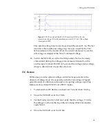
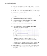
Oscilloscope
channel
1
should
show
a
positive
100
mV
step
followed
by
a
10
mV
ramp
and
then
a
negative
100
mV
step
and
10
mV
ramp.
11.
The
step
should
have
a
rise
time
of
about
50
μ
s.
As
this
is
already
quite
fast,
no
neutralization
of
pipette
capacitance
is
normally
required.
47


