Setup
and
Tutorials
b.
Switch
from
the
BATH
to
the
CELL
position
on
the
CLAMP
‐
1U
model
cell.
c.
Check
the
Pipette
Capacitance
Neutralization
checkbox.
d.
Glide
the
neutralization
value
until
the
leading
edge
of
channel
1
speeds
up
maximally
without
overshoot.
The
value
should
be
between
1
and
3
pF.
7.
Select
TEVC
mode
on
Channel
2.
8.
Enable
Seal
Test.
9.
For
the
SCALED
OUTPUT
signals
select:
a.
Channel
1
“Headstage
1,
Membrane
Potential
(10
mV/mV)”.
b.
Channel
2
“Headstage
2,
0.1×
Membrane
Current
(1
V/
μ
A)”.
10.
Adjust
the
Gain
until
channel
1
starts
to
overshoot.
The
Rise
time
should
be
about
200
μ
s.
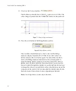
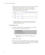
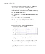
Figure
27.
Voltage
and
current
signals
for
TEVC
mode.
IN0
is
the
membrane
potential
(×10).
IN1
is
the
membrane
current
(1
V/
μ
A).
The
voltage
‐
clamp
Gain
is
200.
Pipette
Capacitance
Neutralization
is
2.5
pF.
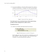
11.
To
optimize
the
voltage
rise
time,
increase
the
Pipette
Capacitance
Neutralization
up
to
an
additional
1
pF
until
the
overshoot
disappears
and
then
increase
the
gain.
Do
not
increase
capacitance
neutralization
or
the
gain
too
high,
as
oscillation
will
result.
With
practice
you
43


