User
Guide
for
Axoclamp
900A
11.
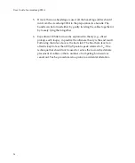
Check
on
the
Tuning
checkbox.
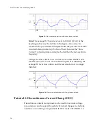
The
Oscilloscope
should
show
a
500
mV
p-p
square
wave
at
10
Hz.
This
is
the
voltage
expected
from
the
50
M
Ω
bath
resistor
in
the
model
cell.
Figure
7.
I
‐
Clamp
voltage
measurement.
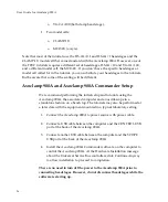
12.
Press
the
Auto
button
in
the
Bridge
Balance
section.
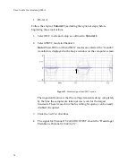
Figure
8.
Bridge
Balance
controls.
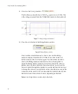
The
waveform
should
decrease
to
close
to
zero
and
the
bridge
resistance
display
should
be
45
to
55
M
Ω
.
If
not,
click
on
the
Lock
button
and
press
the
Auto
button
again.
You
should
also
be
able
to
click
on
the
Bridge
resistance
field
and
use
the
software
glider
to
adjust
the
bridge
balance
resistance.
Note
that
with
all
the
software
gliders,
once
you
have
clicked
on
the
numeric
field,
you
can
use
the
mouse
to
‘glide’
through
the
numbers
or
use
the
keyboard
arrow
keys
to
change
the
value.
If
you
right
click
on
the
value
field
you
can
set
the
coarseness
of
the
control.
You
can
also
enter
the
numbers
directly
into
the
field
or
select
from
allowed
values,
depending
on
the
field.
Note:
Auto
Bridge
Balance
works
only
in
the
bath.
30


