Mitsubishi Electric QJ71GF11-T2 User Manual Download Page 47

45

CHAPTER 3 SPECIFICATIONS

3

3.

5  
Lis
t of
 Buf

fer M

e

mory

 A

ddress

e

s


*1 Since the version of a master/local module is stored, the initial value depends on the master/local module used.

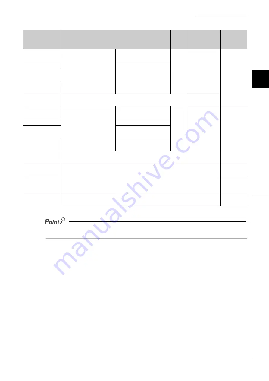
Do not write data to "System area".
Doing so may cause malfunction of the programmable controller system.

30224
(7610

H

)

PORT2 line error occurrence 
rate (max.)

Station No.1

0

Read

Page 472, 
Appendix 2.8

to

to

30343
(7687

H

)

Station No.120

30344
(7688

H

)

Station No.0

30345 to 30351
(7689

to 768F

H

)

System area

30352
(7690

H

)

PORT2 line error occurrence 
rate (present)

Station No.1

0

Read

Page 472, 
Appendix 2.8

to

to

30471
(7707

H

)

Station No.120

30472
(7708

H

)

Station No.0

30473 to 30479
(7709

to 770F

H

)

System area

30480 to 31739
(7710

H

 to 7BFB

H

)

System area

31740  to 32380
(7BFC

H

 to 7E7C

H

)

C Controller module parameter area

Page 537, 
Appendix 7 
(5)

32381 to 32767
(7E7D

H

  to 7FFF

H

)

System area

Address

(Decimal 

(Hexadecimal))

Name

Initial 

value

Read, write

Refer to

Summary of Contents for QJ71GF11-T2

Page 1: ...MELSEC Q CC Link IE Field Network Master Local Module User s Manual QJ71GF11 T2 ...

Page 2: ......

Page 3: ...e safety precautions are classified into two levels WARNING and CAUTION Under some circumstances failure to observe the precautions given under CAUTION may lead to serious consequences Observe the precautions of both levels because they are important for personal and system safety Make sure that the end users read this manual and then keep the manual in a safe place for future reference WARNING CA...

Page 4: ...ion failure For the operating status of each station after a communication failure refer to Page 140 Section 8 1 7 in this manual Incorrect output or malfunction due to a communication failure may result in an accident Do not write any data to the system area of the buffer memory in the intelligent function module Also do not use any use prohibited signals as an output signal from the CPU module t...

Page 5: ... the product To mount the module while pressing the module mounting lever in the lower part of the module fully insert the module fixing projection s into the hole s in the base unit and press the module until it snaps into place Incorrect mounting may cause malfunction failure or drop of the module When using the programmable controller in an environment of frequent vibrations fix the module with...

Page 6: ...tion due to poor contact When disconnecting the cable from the module do not pull the cable by the cable part For the cable with connector hold the connector part of the cable Pulling the cable connected to the module may result in malfunction or damage to the module or cable Use 1000BASE T compliant Ethernet cables for Ethernet connection For the maximum station to station distance and the overal...

Page 7: ...e to do so may cause malfunction Shut off the external power supply all phases used in the system before mounting or removing a module Failure to do so may cause the module to fail or malfunction Tighten the screw within the specified torque range Undertightening can cause drop of the screw short circuit or malfunction Overtightening can damage the screw and or module resulting in drop short circu...

Page 8: ...e of the PRODUCT in Nuclear Power Plants and any other power plants operated by Power companies and or any other cases in which the public could be affected if any problem or fault occurs in the PRODUCT Railway companies or Public service purposes and or any other cases in which establishment of a special quality assurance system is required by the Purchaser or End User Aircraft or Aerospace Medic...

Page 9: ...e end users read this manual Remark Unless otherwise specified this manual describes the program examples in which the I O numbers of X Y00 to X Y1F are assigned for the master local module For I O number assignment refer to the following QnUCPU User s Manual Function Explanation Program Fundamentals COMPLIANCE WITH EMC AND LOW VOLTAGE DIRECTIVES 1 Method of ensuring compliance To ensure that Mits...

Page 10: ...leshooting of the MELSEC L series master local module MELSEC QS CC Link IE Field Network Master Local Module User s Manual SH 080969ENG 13JZ53 Overview of CC Link IE Field Network and specifications procedures before operation system configuration installation wiring settings functions programming and troubleshooting of the MELSEC QS series master local module MELSEC L CC Link IE Field Network Hea...

Page 11: ... name manual number model code Description GX Works2 Version1 Operating Manual Common SH 080779ENG 13JU63 System configuration parameter settings and online operations common to Simple project and Structured project of GX Works2 ...

Page 12: ...on List 36 3 4 List of I O Signals 40 3 5 List of Buffer Memory Addresses 41 CHAPTER 4 PROCEDURES BEFORE OPERATION 46 CHAPTER 5 SYSTEM CONFIGURATION 48 5 1 Overall System Configuration 48 5 2 CC Link IE Field Network Configuration 49 5 2 1 Single network system 49 5 2 2 Multi network system 53 5 2 3 Precautions 54 5 3 Network Components 59 5 3 1 Cables 59 5 3 2 Hubs 60 5 4 Applicable Systems 61 CH...

Page 13: ...rks 145 8 3 IP Packet Transfer Function 146 8 3 1 System configuration of the IP packet transfer function 147 8 3 2 How to set the IP packet transfer function 148 8 3 3 IP communication test 156 8 3 4 Accessible range 158 8 3 5 Relay using CC Link IE Controller Network 159 8 3 6 Precautions 160 8 3 7 Example of communications using the IP packet transfer function 162 8 3 8 Communication speed 172 ...

Page 14: ... to the Programmable Controller on Another Station 283 10 9 JP GP RECV Receiving Data from the Programmable Controller on Another Station 294 10 10 Z RECVS Receiving Data from the Programmable Controller on Another Station 301 10 11 JP GP REQ Remote RUN STOP 307 10 12 JP GP REQ Reading Writing Clock Data 318 10 13 ZP REMFR Reading Data from the Intelligent Device Station Remote Device Station 333 ...

Page 15: ...ocal Module Status by System Monitor 461 APPENDICES 464 Appendix 1 Details of I O Signals 464 Appendix 1 1 Module failure X0 464 Appendix 1 2 Own station data link status X1 464 Appendix 1 3 Other stations data link status X3 465 Appendix 1 4 Module ready XF 465 Appendix 2 Details of Buffer Memory Addresses 466 Appendix 2 1 Link device area Un G0 to Un G18975 466 Appendix 2 2 RX offset size inform...

Page 16: ...7 1 Setting the parameters using the buffer memory in the master local module 531 Appendix 8 New and Improved Functions 546 Appendix 9 Comparison of CC Link and CC Link IE Field Network 548 Appendix 10 Precautions for When Connecting the MELSEC iQ R Series Module 552 Appendix 11 Checking the Serial Number and Function Version 554 Appendix 12 External Dimension Diagram 556 INDEX 558 REVISIONS 561 W...

Page 17: ... for items in the menu bar and the project window shows operating procedures shows reference manuals shows notes that requires attention shows mouse operations 1 shows reference pages shows setting or operating examples Ex shows useful information A window selected in the view selection area is displayed View selection area Online Write to PLC Select Online on the menu bar and then select Write to...

Page 18: ...t name of the software package for the MELSEC programmable controllers Head module The abbreviation for the LJ72GF15 T2 CC Link IE Field Network head module Intelligent device station A station that exchanges I O signals bit data and I O data word data with another station by cyclic transmission This station responds to a transient transmission request from another station and also issues a transi...

Page 19: ...Section 8 1 1 Remote output RY Bit data output from the master station to a slave station For some areas in a local station data are output in the opposite direction Page 124 Section 8 1 1 Remote register RWr Word data input from a slave station to the master station For some areas in a local station data are input in the opposite direction Page 124 Section 8 1 1 Remote register RWw Word data outp...

Page 20: ...U module where the system A connector of a tracking cable is connected in a redundant system System B CPU A CPU module where the system B connector of a tracking cable is connected in a redundant system Transient transmission A function of communication with another station which is used when requested by a dedicated instruction or GX Works2 UINI The abbreviation for Z UINI and ZP UINI WRITE The a...

Page 21: ...19 PACKING LIST The following items are included in the package of this product Before use check that all the items are included QJ71GF11 T2 QJ71GF11 T2 Before Using the Product ...

Page 22: ...n Data is periodically communicated among stations within the same network Page 123 Section 8 1 b Irregular communications transient transmission Data is communicated upon request Page 144 Section 8 2 Master station CPU module X Y W RX RY RWw RWr Local station CPU module Y X W RY RX RWr RWw RX RY RWw RWr RX RY RWw RWr Intelligent device station Intelligent device station Master station Local stati...

Page 23: ... compliant Ethernet cables are commercially available Page 59 Section 5 3 4 Flexible wiring for system arrangements The network can be wired into star topology line topology and ring topology Page 49 Section 5 2 1 For star topology a 1000BASE T compliant switching hub can be used Page 60 Section 5 3 2 Wiring is highly flexible because a network can consist of a combination of star and line topolog...

Page 24: ...e of each master local module is shorter than the scan time of the CPU module Master local modules can perform cyclic transmissions in combination with the following functions Page 36 Section 3 3 Auto transfer of data between the link devices in the master local module and the devices in the CPU module Direct access to the link devices in the master local module by a program Cyclic data assurance ...

Page 25: ...writing data A master local module can access programmable controllers on other stations by dedicated instructions Page 236 Section 10 1 Seamless access of programmable controllers on other networks such as Ethernet CC Link IE Controller Network MELSECNET H and MELSECNET 10 is also possible Command READ Device Device 1234H 1234H CPU module CPU module Master station Local station ...

Page 26: ...ules can be set using GX Works2 Creating parameter setting programs is not necessary Page 81 CHAPTER 7 Parameters for master local modules can be also set by a program Page 359 Section 10 17 When set by a program the parameters of the master station can be changed while the CPU module is running ...

Page 27: ... Checking CC Link IE Field Network status graphically The CC Link IE Field Network status can be checked using GX Works2 Error locations error causes and event history are displayed on the window This allows the system to quickly recover from errors Page 206 CHAPTER 9 ...

Page 28: ... CC Link IE Controller Network MELSECNET H MELSECNET 10 and CC Link Seamless access enables the user to change the access target without modifying the connection between the personal computer and programmable controller GX Works2 CC Link IE field network CC Link IE controller network Network No 2 Network No 1 Relay station Seamless access Systems on other networks can be tested or monitored ...

Page 29: ... be added without powering off the system MELSEC L CC Link IE Field Network Head Module User s Manual MELSEC iQ R CC Link IE Field Network Remote Head Module User s Manual Application b Replacing CC Link IE Field Network devices For star topology slave stations can be replaced without powering off the whole system Connection of an added module can be recognized and setting a station No on the scre...

Page 30: ...r recovers it automatically returns to the network and restarts data link When recovered from fault Master station Station No 0 Slave station Station No 1 Slave station Station No 3 Slave station Station No 2 Return Down Master station Station No 0 Slave station Station No 1 Slave station Station No 3 Slave station Station No 2 ...

Page 31: ...E Field Network and Ethernet are not required resulting in reduced wiring cost Page 146 Section 8 3 In addition communications using the specified IP address can be relayed from CC Link IE Field Network to a different network supporting the IP packet transfer function When relaying communications to CC Link IE Controller Network Ex CC Link IE Controller Network CC Link IE Field Network Relay stati...

Page 32: ...a local station own station can be set using a program When there are local stations with the same program and network parameters excluding the station numbers setting the station numbers using a program allows project data items other than the station number to be the same leading to reduced development work hours Page 380 Section 10 18 Master station station No 0 Master operation Submaster opera...

Page 33: ...ates as a submaster station OFF Operating as a local station MODE LED Indicates the mode ON In online mode Flashing In test mode OFF In offline mode Data link not performed D LINK LED Indicates the status of the data link ON Data link in operation cyclic transmission in progress Flashing Data link in operation cyclic transmission stopped OFF Data link not performed disconnected SD LED Displays the...

Page 34: ... L ERR LED is on you can check the L ER LED for P1 or P2 to see on which port the error was detected The description of the errors can be confirmed in CC Link IE Field Network diagnostics Page 206 CHAPTER 9 This LED automatically turns off when the module has received normal data and loopback is completed in ring topology ON The module has received abnormal data The module is performing loopback o...

Page 35: ...back only the master local module whose serial number first five digits is 12072 or later OFF The module has received normal data The module does not perform loopback only the master local module whose serial number first five digits is 12072 or later LINK LED ON Linkup in progress OFF Linkdown in progress P2 PORT2 connector for CC Link IE Field Network RJ45 connector Connect an Ethernet cable Pag...

Page 36: ...6384 points 2KB RWr 8192 points 16KB RWw 8192 points 16KB When using the submaster function Master operating station RX 16384 points 2KB RY 16384 points 2KB 2048 points and 256 bytes for the send range of an own station RWr 8192 points 16KB RWw 8192 points 16KB 1024 points and 2048 bytes for the send range of an own station 2 Submaster operating station 1 RX 2048 points 256 bytes assigned for the ...

Page 37: ... B Category 5e Page 70 Section 6 3 2 Overall cable distance Line topology 12000m when cables are connected to one master station and 120 slave stations inclusive or exclusive of a submaster station Star topology Depends on the system configuration Ring topology 12100m when cables are connected to one master station and 120 slave stations inclusive or exclusive of a submaster station Number of casc...

Page 38: ...ient transmission frequency The mode can be selected from Online Normal Mode and Online High Speed Mode Page 84 Section 7 2 1 Page 529 Appendix 6 Assurance of cyclic data integrity The cyclic data integrity is assured in units of 32 bits or station based units Page 134 Section 8 1 5 Scan synchronization specification Link scan is set to asynchronous or synchronous with the sequence scan of the CPU...

Page 39: ...CNET H MELSECNET 10 CC Link when using GX Works2 Page 119 Section 7 8 Page 145 Section 8 2 2 Function Description Availability Reference Master station submaster station Local station Slave station disconnection Only the slave station where an error occurs is disconnected and data link continues with the stations that are operating normally In a line topology all stations connected after the fault...

Page 40: ... Field Network can be checked using GX Works2 The error locations error causes corrective actions and event history can be checked in GX Works2 Page 206 CHAPTER 9 Diagnostics of module alone Hardware test The internal hardware of the master local module can be checked Page 64 Section 6 2 1 Self loopback test The communication circuit in the transmission system of the master local module can be che...

Page 41: ...hecked every link scan and if the interrupt conditions are met an interrupt request is made to the CPU module to start the interrupt program Page 107 Section 7 6 Page 177 Section 8 6 IP packet transfer function Communications in a protocol such as FTP and HTTP using the specified IP address of an Ethernet device can be performed over CC Link IE Field Network With this function two networks of CC L...

Page 42: ...l to the QCPU Doing so may cause malfunction of the programmable controller system For details on the I O signals refer to I O Signals Page 464 Appendix 1 Signal direction Master local module CPU module Signal direction CPU module Master local module Device number Signal name Device number Signal name X0 Module failure Y0 Use prohibited X1 Own station data link status Y1 X2 Use prohibited Y2 X3 Ot...

Page 43: ...e 2048 to 10239 800H to 27FFH Remote register RWw 10240 to 18431 2800H to 47FFH Remote register RWr Read 18432 to 18463 4800H to 481FH Link special relay SB 18432 to 18433 for read and write 18434 to 18463 for read only 18464 to 18975 4820H to 4A1FH Link special register SW 18464 to 18495 for read and write 18496 to 18975 for read only 18976 to 19455 4A20H to 4BFFH System area 19456 4C00H RX offse...

Page 44: ...9969 4E01H Station No 1 RWw size to to 20206 4EEEH Station No 120 RWw offset 20207 4EEFH Station No 120 RWw size 20208 4EF0H Station No 0 RWw offset 20209 4EF1H Station No 0 RWw size 20210 to 20223 4EF2H to 4EFFH System area 20224 4F00H RWr offset size information Station No 1 RWr offset 0 Read Page 469 Appendix 2 5 20225 4F01H Station No 1 RWr size to to 20462 4FEEH Station No 120 RWr offset 2046...

Page 45: ...0 Read Page 470 Appendix 2 6 20521 5029H Manufacturer code 20522 502AH Model type 20523 502BH Model code 20524 502CH Version 20525 to 20534 502DH to 5036H Model name string 20535 to 20536 5037H to 5038H Vendor specific device information 20537 to 20538 5039H to 503AH System area 20544 5040H Other station network card information station No 1 Manufacturer code 0 Read Page 471 Appendix 2 7 20545 504...

Page 46: ... 120 Same as other station information station No 1 24384 to 24415 5F40H to 5F5FH Other station information station No 0 Same as other station information station No 1 24416 to 29967 5F60H to 750FH System area 29968 7510H PORT1 line error occurrence rate max Station No 1 0 Read Page 472 Appendix 2 8 to to 30087 7587H Station No 120 30088 7588H Station No 0 30089 to 30095 7589H to 758FH System area...

Page 47: ...age 472 Appendix 2 8 to to 30343 7687H Station No 120 30344 7688H Station No 0 30345 to 30351 7689H to 768FH System area 30352 7690H PORT2 line error occurrence rate present Station No 1 0 Read Page 472 Appendix 2 8 to to 30471 7707H Station No 120 30472 7708H Station No 0 30473 to 30479 7709H to 770FH System area 30480 to 31739 7710H to 7BFBH System area 31740 to 32380 7BFCH to 7E7CH C Controller...

Page 48: ...e with a C Controller module refer to Page 531 Appendix 7 Check box Consider the system configuration and link device assignments System consideration Installation Mount the master local module to the base unit Unit test Perform a unit test on each module Wiring Cable check Perform a cable test on the master local module To the next page Connect an Ethernet cable to each module Page 48 CHAPTER 5 P...

Page 49: ...ate a program Programming Debug the program using the CC Link IE Field Network diagnostics Debug Network diagnostics Perform a loop test on the master station and check if it can properly communicate by the configured parameters Page 81 CHAPTER 7 Page 71 Section 6 4 1 Page 387 CHAPTER 11 Page 206 CHAPTER 9 ...

Page 50: ...CHAPTER 5 SYSTEM CONFIGURATION 5 1 Overall System Configuration This section describes a system configuration example of when using a master local module Master local module Power supply module CPU module ...

Page 51: ... 5 2 1 Single network system 1 Overall system configuration A single network system is a system in which a master station and slave stations are connected using Ethernet cables as shown below Up to 120 slave stations including a submaster station and one master station can be connected Switching hub Ethernet cable 1000BASE T Master station Up to 120 stations 1 station Slave station including a sub...

Page 52: ...ne topology and ring topology A network can consist of a combination of star and line topologies but the ring topology cannot be combined with star or line topology Star topology Line topology Star and line mixed Switching hub Switching hub Switching hub Ethernet cable 1000BASE T Ring topology ...

Page 53: ...added to the network using this topology Data link continues with the stations that are operating normally 1 Line topology The network is configured into a line by connecting the modules with Ethernet cables but without a switching hub If an error occurs stations after the faulty station will be disconnected 1 Ring topology The network is configured into a ring using Ethernet cables but without a ...

Page 54: ...52 c Cascade connection Up to 20 level connection is available for the cascade connection Remark For wiring method refer to Page 68 Section 6 3 Switching hub Up to 20 level cascade connection ...

Page 55: ...can be connected Cyclic transmission communication is available only in the same network Transient transmission communication is available with other networks as well as the same network Communications can be made with stations up to eight networks apart number of relay stations 7 Page 238 Section 10 1 1 b CC Link IE Controller Network CC Link IE Field Network CC Link IE Field Network Network No 3...

Page 56: ...nected modules over occurrence status SB0099 is the total of the slave stations including a submaster station which are currently connected and the disconnected stations slave stations which were previously connected The number of stations which were previously connected can be cleared by executing the network map update of the CC Link IE Field Network diagnostics Page 214 Section 9 3 A data link ...

Page 57: ...2 CC Link IE Field Network Configuration 5 2 3 Precautions Connecting both PORT1 and PORT2 to the switching hub Ring topology through a switching hub Ex Switching hub Cannot connect both Ethernet ports to the switching hub Ex Switching hub ...

Page 58: ...ernet cable is disconnected loopback cannot be detected If a station is disconnected due to failure or power off data link will stop 6 Offline mode station in ring topology In the following cases the master station or the station connected to the offline mode station cannot detect loopback One of the Ethernet cables connected to the offline mode station is disconnected A station connected to the o...

Page 59: ...ve stations may turn off since all stations on the network will be reconnected when executing the network map update Set output data if needed Page 58 Section 5 2 3 8 b When a serial number first five digits of the master station is 17021 or earlier A data link error may momentarily occur in all the stations and outputs of the connected slave stations may turn off since all stations on the network...

Page 60: ... Project window Parameter PLC Parameter I O Assignment button Error Time Output Mode This setting is not required for a head module whose serial number first five digits is 12072 or later 9 Connected station numbers Do not duplicate station numbers Data link may be stopped when the station number is duplicated 10 Power on order To avoid incorrect input from slave stations power on slave stations b...

Page 61: ...ector processing of cable length is available for your preference Please consult your local Mitsubishi Electric System Service Co Ltd Remark Cable types The following cable types are available depending on the operating environment Standard type Cables for inside the control panel and indoor connection L type Cables for outdoor connection Cables and relay adapters of flame retardant or waterproof ...

Page 62: ... MDI X function Support of the auto negotiation function Switching hub layer 2 switch 1 Operation is not guaranteed if the hubs do not meet these conditions 1 A repeater hub is not available 1 Mitsubishi product Type Model name Industrial managed switch NZ2MHG T8F2 Industrial switching hub NZ2EHG T8N NZ2EHG T8 Discontinued model ...

Page 63: ... b Number of mountable modules The number of master local modules that can be mounted depends on the CPU modules For the number of mountable modules refer to the manual for the relevant CPU module c Mounting to a MELSECNET H remote I O station The master local module cannot be mounted to any MELSECNET H remote I O stations Mount the module on a base unit on which a CPU module is mounted CPU module...

Page 64: ...dule Another CPU that does not support the master local module cannot be accessed from another station The following access for example cannot be made Diagnosing e g PLC diagnostics system monitor another CPU that does not support the master local module using GX Works2 To diagnose the CPU connect GX Works2 to the control CPU Accessing another CPU that does not support the master local module usin...

Page 65: ...Prevent foreign matter such as dust or wire chips from entering the module Such foreign matter can cause a fire failure or malfunction A protective film is attached to the top of the module to prevent foreign matter such as wire chips from entering the module during wiring Do not remove the film during wiring Remove it for heat dissipation before system operation Before handling the module touch a...

Page 66: ...eters as shown in the figure to left Project window Parameter Network Parameter Ethernet CC IE MELSECNET 3 Write the network parameters set to the CPU module Online Write to PLC 4 Reset the CPU module or power off and then on the system 5 Hardware test begins The MODE LED of master local modules flashes and each of the 1 LED repeatedly turns on and off 1 2 4 8 1 Select H W Test Select CC IE Field ...

Page 67: ... Doing so may cause the test to fail 6 D LINK LED turns on when the test is completed When completed The 1 LED turns off When failed Any one of the 1 LEDs turns on and the ERR LED turns on When the test fails the possible cause is hardware failure of the master local modules Please consult your local Mitsubishi representative with the detailed problem description Item Description When completed Ha...

Page 68: ...work parameters as shown in the figure to left Project window Parameter Network Parameter Ethernet CC IE MELSECNET 3 Write the network parameters set to the CPU module Online Write to PLC 4 Connect PORT1 and PORT2 of the mater local modules with an Ethernet cable Page 68 Section 6 3 5 Reset the CPU module or power off and on the system Select Self Loopback Test Select CC IE Field Master Station CC...

Page 69: ...te the test again If the test fails replace the Ethernet cable and execute the test again If the test fails again the possible cause is hardware failure of the master local modules Please consult your local Mitsubishi representative with the detailed problem description Item Description When completed Self loopback test completion status SB0092 ON Self loopback test normal abnormal end SB0093 OFF ...

Page 70: ...clicks Pay attention to the connector s direction 3 Power on the master local module and the connected device 4 Check whether the LINK LED of the port connected with an Ethernet cable is on The time between the power on and the LINK LED turning on may vary The LINK LED usually turns on in a few seconds Note however that the time may be extended further if the linkup process is repeated depending o...

Page 71: ...he cable can be connected between PORT1s or between PORT1 and PORT2 b Disconnecting the cable 1 Power off the system 2 Press the latch down and unplug the Ethernet cable LINK P1 L ER QJ71GF11 T2 LINK P2 L ER Either one can be used LINK P1 L ER LINK P2 L ER LINK P1 L ER LINK P2 L ER LINK P1 L ER LINK P2 L ER LINK P1 L ER LINK P2 L ER LINK P1 L ER LINK P2 L ER LINK P1 L ER LINK P2 L ER QJ71GF11 T2 Q...

Page 72: ...lfunction due to incorrect installation of the cable b Broken cable latch Do not use Ethernet cables with broken latches Doing so may cause the cable to unplug or malfunction c Connecting and disconnecting the Ethernet cable Hold the connector part when connecting and disconnecting the Ethernet cable Pulling a cable connected to the module may damage the module or cable or result in malfunction du...

Page 73: ... a network Submaster station duplication check Checks if more than one submaster station exists on a network Station number duplication check Checks if stations on the network are duplicated Out of range station No check Checks if the number of connected slave stations exceeds the number of slave stations set to the master station Reserved station specification check Checks if the specified reserv...

Page 74: ... If a loop test is executed with the station number not set the loop test abnormally ends 1 Connect GX Works2 to the CPU module 2 Set slave stations and the submaster station to the online mode 3 Reset the slave stations or power off and on to set the mode to online When setting the master station to the loop test mode set the submaster station to the online mode Master station Slave station Selec...

Page 75: ...ower off and on the system When the submaster station has been connected reset the submaster station then master station or power off and on the system within two seconds 6 Loop test begins Master station The MODE and D LINK LEDs flash Also each of the 10 LED and 1 LED repeatedly turns on and off 1 2 4 8 1 However if errors are detected the test is immediately terminated failure Slave station Data...

Page 76: ...e mode Set the master station to online mode through the network parameter RUN SD ERR MST D LINK RD L ERR 1 2 4 8 MODE X100 10 1 S T N O 1 2 4 8 1 RUN SD ERR MST D LINK RD L ERR 1 2 4 8 MODE X100 10 1 S T N O 1 2 4 8 1 On When completed Flashing On When failed Flashing 1 1 2 4 8 1 2 4 8 10 Master station overlap submaster station overlap Station No overlap Invalid station No Reserved station speci...

Page 77: ...t status and result can be viewed through monitoring the link special relays SBs on GX Works2 Item Description When completed Loop test completion status SB0094 ON Loop test normal abnormal end SB0095 OFF When failed Loop test completion status SB0094 ON Loop test normal abnormal end SB0095 ON ...

Page 78: ...indow Diagnostics CC IE Field Diagnostics 2 The error location is displayed in Network Status 3 Click the error location 4 Click the button displayed in Selected Station Communication Status Monitor to display the error descriptions Take corrective actions according to the error description 5 Reset the CPU module on the master station or power off and on the system to retry the loop test Click or ...

Page 79: ...or details by directly connecting GX Works2 to the faulty station and displaying the system monitor window Page 461 Section 12 6 b Checking by link special register SW Identify the error location by link special register SW and take actions After the actions execute the loop test again 1 Check Loop test result SW0194 for error details Check the station number where a loop test error occurs using L...

Page 80: ...For the whole network status perform the loop test Page 71 Section 6 4 1 1 Connect GX Works2 to the CPU module 2 Open the Cable Test window Diagnostics CC IE Field Diagnostics button 3 Enter a station number and click the button to operate the test If an error occurs take corrective actions according to the error message Station No 0 Station No 1 Station No 2 Station No 3 ...

Page 81: ...on 1 Station No 2 Station No 3 Relay station 2 Station No 1 Network No 1 Network No 3 Network No 2 GX Works2 Communication target Own station request source CC Link IE Field Network CC Link IE Field Network CC Link IE Field Network Station No 2 Station No 1 Station No 3 Station No 0 Station No 0 Station No 2 Station No 4 Station No 0 Relay station 1 Station No 2 Station No 3 Relay station 2 Statio...

Page 82: ...nder Target Station set a station mounted on a different base unit from the station set in Connected Station Own 3 Write the network parameters set to the CPU module Online Write to PLC 4 Reset the CPU module or power off and on the system 5 Open the Communication Test window and enter values for Target Station and Communication Data Setting Diagnostics CC IE Field Diagnostics button 6 Click the b...

Page 83: ... using GX Works2 for the parameter setting select Specify Station No by Program in the station number setting method Then set the station number using the UINI instruction When using the CCPASET instruction for the parameter setting set Switch 2 in the intelligent function module switch setting to 31FFH After setting the network parameters using the CCPASET instruction set the station number using...

Page 84: ...aster station Network setting Network Type Page 84 Section 7 2 Start I O No Network No 1 Total Stations 1 Station No Mode Network Configuration Settings Station No 1 Page 88 Section 7 3 Station Type RX RY Setting RWw RWr Setting Reserved Error Invalid Station Alias Comment Supple mentary setting Link Scan Mode Setting Loopback Function Setting Block Data Assurance per Station Operation Setting for...

Page 85: ...rformed 2 Parameters set for slave stations For the parameters of a slave station refer to the manual for the slave station used Network Operation Settings Parameter Name Page 101 Section 7 4 Data Link Faulty Station Setting Output Setting During CPU STOP Set IP address 1 Refresh Parameters Page 103 Section 7 5 Interrupt Settings Page 107 Section 7 6 Station number setting method Page 84 Section 7...

Page 86: ...he CC IE Field configuration window to set the network configuration setting The checkbox is not checked Use the CC IE Field configuration window to set the network configuration setting The checkbox is checked Default Do not use the CC IE Field configuration window to set the network configuration setting The checkbox is not checked Network Type Select whether to use the master local module as a ...

Page 87: ...he setting value in the CC IE Field configuration setting window is displayed Master station 1 to 120 Default Blank Submaster station 0 or same as the master station setting Default 0 Station No Enter the station number of the master local module Set a station number different from those used in the same network The station number of the master station is fixed to 0 To set the station number of a ...

Page 88: ...f data for management monitoring and diagnostics by transient transmission Page 529 Appendix 6 Use this mode for general applications Online High Speed Mode This mode preferentially performs cyclic transmission for high speed communications This mode is suitable for a system to achieve I O control analog control and digital I O at high speed Page 529 Appendix 6 Note that the maximum number of poin...

Page 89: ...for a local station When selecting Specify Station No by Program set the station number using the UINI instruction Page 380 Section 10 18 Specify Station No by Parameter Specify Station No by Program Default Specify Station No by Parameter Configure the setting for the submaster station Whether to operate the number of link device points and assignment in the slave station according to the paramet...

Page 90: ...ork configuration can be set while checking the CC Link IE Field Network configuration graphically Slave stations are added by selecting the model name displayed on the window therefore a setting error in the station type can be prevented Unlike the setting on the window in the table format the following can be performed Change transmission path method Page 91 Section 7 3 1 b Parameter processing ...

Page 91: ...Parameter Ethernet CC IE MELSECNET button 4 Select the module under Module List and drag and drop it to the station list area or the device map area The slave station is added to the station list area The added module is displayed in the device map area 5 Configure the setting of each item described after a 6 After the setting is completed close the window CC IE Field Configuration Close with Refl...

Page 92: ...mon STA Enter the station number of each slave station or the submaster station connected to the network Station numbers do not need to be set consecutively but must be unique The station number of the master station is fixed at 0 1 to 120 Default Blank Station Type Select the station type excluding the master station Select the station type same as that of the modules connected to the network Rem...

Page 93: ...fore the program needs not to be modified Physical connection of the slave station is not required Error Invalid Station Even if a slave station is disconnected during data link the master station will not detect the slave station as a faulty station No Setting Reserved Station Error Invalid Station Default No Setting Alias Enter the name of a device if required The name entered is displayed in Ne...

Page 94: ...Item Description Setting range Change Transmission Path Method Change the transmission path method The loopback function can be used by selecting Ring Page 178 Section 8 7 Line Star Ring Default Line Star ...

Page 95: ...will become longer Constant Scan Cyclic transmission is performed punctually Link scan time will be the constant link scan time set in this setting However when the actual link scan time is longer than the specified link scan time cyclic transmission is performed by actual link scan time While constant link scan is used to keep link scan time constant the transmission delay time is not kept consta...

Page 96: ...sis in link refresh between the CPU module and the master local module Page 134 Section 8 1 5 4 Operation Setting for Returning When using the submaster function select the operation of the master station after it returns from the disconnected status This parameter can be set only when Sub Master Station has been selected in Station Type Loopback Function Setting Selected Use not selected Default ...

Page 97: ...preset conditions Start Station 0 to the end station number End Station Number set to Start Station to the end station number Start No Same values set in RX RY Setting and RWw RWr Setting Total Points Assigned Same values set in RX RY Setting and RWw RWr Setting Default Blank Identical Point Assignment Assign the same link device points to all stations Points entered in this field will be reflecte...

Page 98: ...E Field Configuration Command Execution of Slave Station The command of a slave station is executed This can be performed when the slave station supports the command execution The setting range varies depending on the target module For details refer to the manual for the slave station used ...

Page 99: ...rt and end numbers of link devices Points Start Start End Default Start End Module No The number of stations set in Total Stations of the network settings is displayed Station No Select the station type excluding the master station Select the station type same as that of the modules connected to the network 1 to 120 Default Stations are numbered in consecutive order by the number of stations set i...

Page 100: ...slave station is connected to the network Reserved Station The slave station is reserved for future expansion By reserving a slave station link device assignment will not change even if the slave station is added or the reservation is cancelled Therefore the program needs not to be modified Physical connection of the slave station is not required Invalid Station Even if a slave station is disconne...

Page 101: ...urn as Master Station Return as Sub Master Station Default Return as Master Station Item Description Setting range 1 Link Scan Mode Setting Item Description Asynchronous Link scan is performed asynchronously with the sequence scan of the CPU module Select this item to shorten input transmission delay time when sequence scan takes much time than link scan Note that output transmission delay time wi...

Page 102: ... in the field right next to the button Points entered in this field will be reflected to the Points of RX RY Setting Half of the points entered in this field will be reflected to the Points of RWw RWr Setting Item Description Setting range Item Description Start Station Enter the start station number of stations for which link devices are equally assigned End Station Enter the end station number o...

Page 103: ...t CC IE MELSECNET button 3 Set parameters in the window Item Description Setting range Parameter Name Enter the name of network operation setting parameters if desired Up to 8 characters Data Link Faulty Station Setting Select whether to hold or clear data input from the slave station where a data link error has occurred Page 140 Section 8 1 7 Turn OFF or 0 Clear Input Data RX RY Hold Input Data D...

Page 104: ...same network address for the request source device request destination device and modules among them Whether the network address of the master station matches with that of the submaster station can be checked using IP address setting status SB0080 Since automatically assigned an IP address needs not to be set for local stations The network address same as that of the master station is automaticall...

Page 105: ...umbers of link devices Start End Enter the start and end numbers of link devices Points Start Start End Default Start End Transfer SB Transfer SW Dev Name Set the link refresh ranges of SB and SW One range can be set for each SB and SW Page 127 Section 8 1 2 1 Transfer SB Link Side Fixed at SB PLC Side M L B D W R SB ZR 2 Transfer SW Link Side Fixed at SW PLC Side M L B D W R SW ZR Default Blank P...

Page 106: ...tart End Link Side 0 to 3FFFH for RX RY 0 to 1FFFH for RWr RWw PLC Side Within device range of CPU module Default Blank Set bit devices in increments of 16 points and word devices in increments of 4 points button Reset refresh parameters to default Item Description Setting range Ex Device name RX Device name RY Device name RWr Device name RWw Device name W Device name W Device name Y Device name X...

Page 107: ...devices to be checked and the magnification ratio in the window 3 A red part in the device of the CPU module indicates that the device range overlaps with the device range set for other refresh parameters Correct the refresh parameters The link devices of the master local module can be accessed from a program Page 129 Section 8 1 3 1 Click 2 Set Device PLC side Device Link side and Display magnifi...

Page 108: ...PU module for link refresh range Doing so will reduce link refresh points resulting in a shorter link refresh time c Changing link device assignment in the Network Configuration Settings window Correct the link refresh ranges of refresh parameters d Setting an extended data register D or extended link register W as a link refresh device Set the link refresh range properly so that it does not cross...

Page 109: ...e set in Device Code and Device No Interrupt Condition Word Device Setting Value When RWw RWr or SW is selected in Device Code enter a word device value that triggers an interrupt Channel No Connection No When RECVS Instruction is selected in Device Code enter the channel number of the RECVS instruction used for trigger condition A channel is an area in a network module Data used by link dedicated...

Page 110: ...FF Interrupt occurs at the falling edge of the device 0 to 15 RY 0H to 3FFFH SB 0H to 1FFH RWr 0H to 1FFFH Level Detect and Equal Interrupt occurs when values match Level Detect and Unequal Interrupt occurs when values do not match Edge Detect and Equal Interrupt occurs when values match first time only Edge Detect and Unequal Interrupt occurs when values do not match first time only 0 to 65535 0H...

Page 111: ...e When Level Detect is set for Detection Method and the interrupt condition is always met do not use interrupt settings and correct the interrupt condition in the program b Before executing an interrupt program Execute the EI instruction in a main routine program and enable an interrupt User s Manual Function Explanation Program Fundamentals for the CPU module used c When multiple interrupts simul...

Page 112: ...g on RX100 in a station in network number 7 f An interrupt cannot be generated Changes in the interrupt condition device cannot be detected if the change is shorter than the transmission delay time g Using cyclic data in an interrupt program When an interrupt program is executed link refresh is not performed to CPU module devices Directly access the link devices of the master local module by direc...

Page 113: ...e master local module station number 0 in the Interrupt Settings window as shown below 2 Set the parameters in the Intelligent Function Module Interrupt Pointer Setting window as shown below By using link special relay SB and link special register SW as an interrupt condition device an interrupt program can be started in case of data link error Page 473 Appendix 3 Page 493 Appendix 4 1 2 RX100 I50...

Page 114: ...tation number 1 using the SEND instruction in channel 2 1 Set the interrupt setting parameters for the master local module station number 0 in the Interrupt Settings window as shown below 2 Set the parameters in the Intelligent Function Module Interrupt Pointer Setting window as shown below 1 2 3 I52 SM400 IRET RECVS Interrupt program execution Channel 2 Channel 1 Channel 2 SEND Master station Sta...

Page 115: ...source module and transfer target module in the left side area and enter setting values in the right side area of the window 4 Click the button Item Description Setting range Assignment Method Select a link device assignment method Points Start Enter the points and start numbers of link devices Start End Enter the start and end numbers of link devices Points Start Start End Default Start End Trans...

Page 116: ...ents of 4 RWr 0H to 1FFFH RWw 0H to 1FFFH Default Blank Transfer To Item Description Setting range When the transfer source is a master local module 1 1 1 1 When the transfer target is a master local module Start RX No 1 No 2 Master local module Master local module Network module Network module LB LB End Start End Start End Start End RX Start LB RY RY End Start End Start End Start End LB No 64 No ...

Page 117: ...indow 6 Select the devices to be checked and magnification ratio in the window Select the devices and magnification ratio in Device PLC Side Device Link Side and Display Magnification 7 A red part in the transfer target link device indicates that the device range overlaps with the link refresh range set for refresh parameters Correct the interlink transmission parameters or refresh parameters Clic...

Page 118: ...be overwritten by link refresh To use transfer target link device data in the CPU module set the transfer source link device as the link refresh range d Setting 65 or more interlink transmission ranges Use link direct devices in a program to perform interlink transmission Transfer source Link refresh range 1 Link refresh range 2 CPU module Network module 1 Network module 2 Master station Station N...

Page 119: ...a input from the slave station station number 1 is transferred 1 Select CC IE Field Master Station for Transfer From and CC IE Control Normal Station for Transfer To and enter the transfer ranges of link devices 2 Click the button 128 points Slave station Station No 1 CC Link IE Controller Network CC Link IE Field Network Master station Station No 0 Normal station Station No 4 Station No 1 send ra...

Page 120: ... s send range of the network module If the link devices are set within another station s send range the transferred data are overwritten with another station s send data 1000 103F 0 3F 0 1000 0 LB RX Set this within its own station send range of the network module Own station send range Other station send range Master station Station No 0 Network module ...

Page 121: ...he parameters need to be set in the following cases To perform transient transmission with stations on different networks using dedicated instructions Page 236 CHAPTER 10 To use the IP packet transfer function Page 146 Section 8 3 1 Setting procedure 1 Open the setting window Project window Parameter Network Parameter Ethernet CC IE MELSECNET button 2 Set parameters in the window 3 Click the butto...

Page 122: ...uting parameters set for the master station Item Description Setting range Target Network No Set a relay station of the own network to send data to a station on another network by transient transmission Up to 64 communication paths can be set Set routing parameters as shown below Setting to transmit data to network number by transient transmission 1 to 239 Default Blank Relay Network No 1 to 239 D...

Page 123: ...stem Set the same routing parameters to all the control CPUs b When multiple master local modules with the same network number are connected to one system Set the station number of a module with the smallest slot number in Relay Station No In a multiple CPU system set the station number of a module with the smallest slot number regardless of the CPU number of the control CPU 1 2 1 2 1 2 Control CP...

Page 124: ... reach network No 1 Passes data to the request source on network No 1 Automatically passes data to the relay station Setting for relay station 2 Setting for request source Network No 1 CC Link IE Field Network Master station Station No 0 Station No 5 Station No 1 Station No 4 Station No 2 Station No 3 Station No 1 Station No 4 Station No 5 Station No 4 Station No 1 Station No 2 Station No 3 Reques...

Page 125: ...ransmission CHAPTER 8 FUNCTIONS This chapter describes the functions of the master local module 8 1 Cyclic Transmission Data communication is available periodically among stations on the same network Link devices RX RY RWr and RWw are used ...

Page 126: ...ata of the link devices RY and RWw of the slave station are output to the external device The status data of the external device are stored in the link devices RX and RWr of the slave station The status data of the link devices RX and RWr of the slave station are stored in the link devices RX and RWr of the master station by link scan The status data of the link devices RX and RWr of the master st...

Page 127: ...red in the own station send range of the link device RY RWw The status data of the link device RY RWw of the local station is stored in the link device RX RWr of the master station by link scan The status data of the link device RX RWr of the master station is stored in the device of the CPU module by link refresh 1 8 2 4 6 5 3 7 Local station RX RWr RY RWw Station No 1 Local station RX RWr RY RWw...

Page 128: ... RWr RY RWw Station No 1 Slave station RX RWr RY RWw Station No 2 RX RWr RY RWw Station No 3 RX RWr RY RWw Station No 0 Local station Master station Area where data is sent to other stations Range of the station No 1 sending data Range of the station No 2 sending data Range of the station No 3 sending data Range of the sending data to the station No 1 Range of the sending data to the station No 2 ...

Page 129: ...reducing the number of link refresh points to the CPU module The following methods can be used to reduce the number of the link refresh points In the refresh parameters setting set only the link devices used in the CPU module as the link refresh range Page 103 Section 7 5 Directly access infrequently used link devices from the program and remove the corresponding settings from the link refresh ran...

Page 130: ... the CPU module device column in the table below may be output depending on the timing of the link scan and link refresh even if the data are cleared to zero on a sequence program Take the following actions not to output the data in the latched devices 1 For the initial device value setting refer to the user s manual Function Explanation Program Fundamentals for the CPU module used CPU module devi...

Page 131: ...he link device of the master local module for reading or writing J Remote register RWw W0 to W1FFF Remote register RWr W2000 to W3FFF Remote input RX X0 to X3FFF Remote output RY Y0 to Y3FFF Link special relay SB SB0 to SB1FF Link special register SW SW0 to SW1FF Network No 1 to 239 MOV K20 J1 W100 J1 W2100 K300 J1 X1100 J1 Y1000 Master station Slave station Network No 1 Actual I O Master local mo...

Page 132: ...nge that satisfies all of the following conditions can be specified Area where data is sent to other stations and outside the link refresh range Page 124 Section 8 1 1 Within the link device range of the master local module Page 129 Section 8 1 3 1 Y RY Ex CPU module Master local module This area is writable Link refresh Link refresh Area where data is sent to other stations Outside the link refre...

Page 133: ... W100 MOV K20 J1 W100 MOV K20 W100 RWw 20 300 RWw100 RWw100 W 300 W100 W100 Master local module Link refresh overwrites the value The value written by direct access is reflected Master local module CPU module CPU module Write the same data to the CPU module Bad example Only direct access to the link refresh target RWw 20 W 20 Link refresh Link refresh Good example In addition to direct access writ...

Page 134: ...fresh points to the CPU module resulting in a shorter link refresh time Page 127 Section 8 1 2 b Shortening the transmission delay time Because the link direct device allows direct reading or writing of data to the link devices of the master local module at the time of the instruction execution the transmission delay time can be shortened Remark Link refresh is executed in END processing of the se...

Page 135: ...on transfers the link devices of the master station and submaster station to another network module 1 Setting method Interlink transmission is set by the interlink transmission parameters Page 113 Section 7 7 2 Precautions For the precautions refer to Page 113 Section 7 7 Relay station Interlink transmissions Network module Master local module Network No 1 Network No 2 Data of network No 2 Data of...

Page 136: ...ing When there is a remote device station in the network enable block data assurance per station Method Description Assurance Link refresh Direct access to link devices Access to buffer memories 32 bit data assurance Assures data in 32 bit units Data is automatically assured by satisfying assignment conditions of link devices Block Data Assurance per Station Assures data in station based units Dat...

Page 137: ...ess of the buffer memory is multiples of 2 For data assurance of more than 32 bits use the block data assurance per station or interlock programs 2 words 32 bits 0H Access by using start device No which is a multiples of 2 and in 2 word 32 bit units 1H 2H 3H 4H 5H 6H 7H RWr RWw Master local module Device CPU module Link refresh 2 words 32 bits 2 words 32 bits 2 words 32 bits 2 words 32 bits 2 word...

Page 138: ...grity of the data for all stations is assured for each station When there is a remote device station in the network enable block data assurance per station b Access to link devices During a link refresh data are assured for each station as shown below Select the checkbox Station No 1 Station No 2 Station No 3 Station No 4 Data assurance Data assurance Data assurance Data assurance Data assurance D...

Page 139: ...0 of the sending station for a handshake Cyclic transmission sends RWw followed by RY and X1000 of the receiving station turns on The contents of W1000 to W1003 are stored in D0 to D3 Upon completion of storage in D0 to D3 turn on Y1000 of the receiving station for a handshake When X1000 of the sending station turns on turn off Y1000 of the sending station When X1000 of the receiving station turns...

Page 140: ...ving station is turned on The contents of W1000 to W1003 are stored in D0 to D3 Upon completion of storage in D0 to D3 turn on B0 of the receiving station for a handshake When B1000 of the sending station turns on turn off B0 of the sending station When B1000 of the receiving station turns off turn off B0 of the receiving station 8 1 4 5 2 3 7 6 Cyclic transmission Link refresh Send request SET B0...

Page 141: ...h time than link scan Note that output transmission delay time will become longer b Synchronous setting Link scan is performed synchronously with the sequence scan of the CPU module Select this item in the following cases To shorten output transmission delay time Note that when sequence scan takes much time than link scan input transmission delay time will become longer To keep transmission delay ...

Page 142: ...tion can be selected Master station RX RY Station No 0 Area for which Clear or Hold can be selected in the data link faulty station input status setting Area for which Clear or Hold can be selected in the cyclic output setting for a stop error of the CPU module Area where data are held regardless of the setting Area that depends on the setting of the slave station other than a local station Statio...

Page 143: ... When data link is stopped by users When cyclic transmission is stopped using one of the following methods the input status of the faulty station is held CC Link IE Field Network diagnostics Page 221 Section 9 4 Link special relay SB link special register SW Page 408 Section 11 4 1 b Setting on a station with a data link error When the following settings are set to Hold on the station where a data...

Page 144: ...ng method Set the output status for the case where the CPU module switch is set to STOP Select hold or clear in the Network Operation Settings window Page 101 Section 7 4 3 Precautions a When the output setting during CPU STOP is set to clear When the CPU module is in the STOP status the forced output to slave stations cannot be executed using GX Works2 b When refreshing data by a link direct devi...

Page 145: ...yclic transmission stop and restart During debugging and other operations cyclic transmission is stopped Data reception from a slave station and data sending from the own station are stopped Also the stopped cyclic transmission can be restarted Transient transmission does not stop Page 221 Section 9 4 ...

Page 146: ...e same network Transient transmission can be performed to other stations through dedicated instructions or GX Works2 Page 236 CHAPTER 10 With a dedicated instruction READ accessing a programmable controller of another station With GX Works2 the remote operation and clock settings cannot be set in units of groups on CC Link IE Field Network Ex 1 2 3 Command READ Device Device 1234H 1234H CPU module...

Page 147: ...ilable with the following networks Page 119 Section 7 8 Ethernet CC Link IE Controller Network MELSECNET H MELSECNET 10 CC Link when using GX Works2 Communications can be made with stations up to eight networks apart number of relay stations 7 Page 238 Section 10 1 1 b With GX Works2 the remote operation and clock settings cannot be set in units of groups on CC Link IE Field Network Set the commun...

Page 148: ...rocess Service process by a sequence scan of a CPU module Link scan on CC Link IE Field Network Because of this the speed of communications using the IP packet transfer function is slower than the speed of communications with the Ethernet line The reference speed of communications using the IP packet transfer function is described in Page 172 Section 8 3 8 Ethernet Two networks were required Only ...

Page 149: ...le supporting the CC Link IE Field Network gateway setting Connect an Ethernet device to a module such as an Ethernet adapter module supporting the CC Link IE Field Network gateway setting Doing so allows communications to be performed with an Ethernet device having a different network address Ethernet device request source device Ethernet device request destination device Only Built in Ethernet p...

Page 150: ...the CPU module drops under heavy load causing other service processes to be slow or other problems For the gateway address setting of when an Ethernet device is connected to a module other than a CPU module refer to the manual for the module connected to the Ethernet device Checking after the setting is completed Execute the IP communication test to check for an error in the communication route Pa...

Page 151: ... to 120 125 125 is always set in the master station Universal model QCPU on the communication route not connected to an Ethernet device IP address setting not required Use the same numbers for the first and second octets of the IP addresses of the request source device request destination device and modules between them network address Set the third and fourth octets of the IP address within the r...

Page 152: ...t transfer function QJ71E71 100 Ethernet interface module 3 Ethernet device request source device 192 168 10 11 192 168 10 36 192 168 2 125 192 168 7 18 192 168 2 8 Network No 10 Network No 2 Built in Ethernet port QCPU Master station Station No 0 Universal model QCPU Local station Station No 8 Local station Station No 18 IP address setting not required 4 192 168 10 1 192 168 21 2 192 168 10 2 Eth...

Page 153: ...t use the IP addresses already used for other devices Device to be set Setting range of the IP address First and second octets Third octet Fourth octet Ethernet device Within the range applicable to the Ethernet device Module supporting the CC Link IE Field Network gateway setting Within the range applicable to the module supporting the CC Link IE Field Network gateway setting Manual for the modul...

Page 154: ...2 Section 8 3 7 a Setting in the CPU module 1 Open the Q Parameter Setting window to set the IP address Project window Parameter PLC Parameter Built in Ethernet Port Setting Follow the rules to set the address Page 149 Section 8 3 2 1 2 Click the button Then select Use ...

Page 155: ...arameters refer to the following Item Description Target Network No Set the own network station where communications are transmitted through to reach the Ethernet device Set the routing parameters for all the CPU modules on the communication route Set the routing parameters as follows When the network address of the Ethernet device and CPU module is the same as that of the master station Relay Net...

Page 156: ... routing parameters to the master station Network No 3 Target Network No Relay Network No Relay Station No The setting is not required because the module does not have the routing parameters Set this column to pass communications through the master station Target Network No Relay Network No Relay Station No 3 0 2 1 1 2 3 2 2 Station No 2 Station No 1 Setting for A Setting for B Setting for C Stati...

Page 157: ... not required for the local stations The same network address as the master station is automatically assigned to the first and second octets The network number of the own station is assigned to the third octet and the station number of the own station is assigned to the fourth octet 1 Open the Network Operation Settings window Project window Parameter Network Parameter Ethernet CC IE MELSECNET but...

Page 158: ... transfer function The following system configuration is used to explain the procedure of the IP communication test The IP communication test allows the communication paths in the dotted line above to be checked 1 Set parameters for the CPU module and master local module Page 148 Section 8 3 2 2 Write the set parameters to the CPU module using GX Works2 Online Write to PLC 3 Reset the CPU module o...

Page 159: ...device request destination device can be checked using the IP communication test For the IP communication test performed from an Ethernet adapter module refer to the manual for the Ethernet adapter module 4 Open the IP Communication Test window Enter the IP address of the CPU module or the master local module connected to the request destination device in Communication Target When the module that ...

Page 160: ...e connected Range of communications of when and are Ethernet devices with an IP address that does not meet the IP address setting rules Different network addresses Value other than 1 to 239 Value other than 1 to 120 IP address that does not follow the IP address setting rules 10 11 250 150 Ex 3 4 Modules not supporting the CC Link IE Field Network gateway setting Ethernet adapter module 1 Ethernet...

Page 161: ...relay from CC Link IE Field Network to CC Link IE Controller Network When using the IP packet transfer function on CC Link IE Controller Network refer to the following Manual for the CC Link IE Controller Network module used CC Link IE Controller Network CC Link IE Field Network Relay station Ethernet Ethernet Ethernet Ethernet Request source Request destination 2 Request destination 3 Request des...

Page 162: ...s is established the D LINK LED turns off The IP packet transfer function can be used before a baton pass is established If communications are performed before that a timeout error occurs in an Ethernet device request source device Whether the baton pass is established in the own station can be checked on the D LINK LED 3 Using other networks Communications cannot be performed via modules that do ...

Page 163: ... number are connected to one system the master local module with the smallest slot number transfers the IP packet To transfer the IP packet connect the Ethernet device to a control CPU of the master local module with the same network number and smallest slot number 1 2 3 Ethernet Ethernet Ethernet device request source device CC Link IE Field Network Control Ethernet device request destination dev...

Page 164: ...er station station number 0 1 Set the IP address in the CPU module 1 Project window Parameter PLC Parameter Built in Ethernet Port Setting Ethernet device request source device 192 168 1 1 Route through which IP packets are passed Routing parameters must be set Network No 1 Network No 10 CPU module 1 192 168 1 10 Master station station No 0 192 168 2 125 CPU module 2 192 168 10 10 Local station st...

Page 165: ...in Ethernet Port Setting button 3 Set the routing parameters in the CPU module 1 Project window Parameter Network Parameter Ethernet CC IE MELSECNET button 4 Set the IP address in the master station station number 0 Project window Parameter Network Parameter Ethernet CC IE MELSECNET button 5 Write the set parameters to the CPU module 1 Then reset the CPU module 1 or power off and on the system Onl...

Page 166: ... number 2 1 Set the IP address in the CPU module 2 Project window Parameter PLC Parameter Built in Ethernet Port Setting 2 Configure the IP packet transfer setting in the CPU module 2 Project window Parameter PLC Parameter Built in Ethernet Port Setting button ...

Page 167: ...line Write to PLC c Checking the status of communications After the setting is completed in each module execute the IP communication test to check for an error in the communication route on CC Link IE Field Network Page 156 Section 8 3 3 When the IP communication test is normally completed The following window appears When the IP communication test ends abnormally If the test ends abnormally click...

Page 168: ...ion tool to set the IP address in the Ethernet adapter module 1 Ethernet part Setting item tree NZ2GF ETB Parameter Ethernet 2 The IP address setting is not required for the Ethernet adapter module 1 CC Link IE Field Network part The network address set in the master station 1 station number 0 is automatically assigned No Module transferring the IP packet IP address Ethernet adapter module 1 stati...

Page 169: ...e 1 Setting item tree NZ2GF ETB Parameter CC Link IE Field Network Configure the setting as follows 4 Write the set parameters to the Ethernet adapter module 1 Online Write Station where the IP packet passes through last Network No station No To transmit communications to the request destination the IP packet passes through the station with the network address No and station No Request source Requ...

Page 170: ... part does not have a network number Set the communication route to the network number 2 Project window Parameter Network Parameter Ethernet CC IE MELSECNET button 2 Set the IP address in the master station 1 station number 0 Project window Parameter Network Parameter Ethernet CC IE MELSECNET button 3 Write the set parameters to the CPU module 1 Then reset the CPU module or power off and on the sy...

Page 171: ...etwork Parameter Ethernet CC IE MELSECNET button 2 Set the IP address in the master station 2 station number 0 Project window Parameter Network Parameter Ethernet CC IE MELSECNET button 3 The IP address setting is not required for the local station 1 station number 2 The network address set in the master station 1 station number 0 is automatically assigned 4 Write the set parameters to the CPU mod...

Page 172: ...e 2 CC Link IE Field Network part The network address set in the master station 2 station number 0 is automatically assigned 3 The CC Link IE Field Network gateway setting is not required for the Ethernet adapter module 2 Because the network address of the request destination Ethernet adapter module 1 is the same as that of the master station setting only the communication route in the routing par...

Page 173: ...source device and Ethernet device request destination device Online Diagnostics button For the IP communication test using the configuration tool refer to the following CC Link IE Field Network Ethernet Adapter Module User s Manual When the IP communication test is normally completed The following window appears When the IP communication test ends abnormally If IP communications cannot be performe...

Page 174: ...ofessional Operating System Ethernet board 1000BASE T FTP client application FFFTP Ethernet device request destination device FTP server CPU Intel Core i5 processor 2 67GHz OS Microsoft Windows 7 Professional Operating System Ethernet board 1000BASE T FTP server application FileZilla Server Programmable controller CPU module Q06UDEHCPU Sequence scan time 1ms Service processing setting performed ac...

Page 175: ...munication speed The following table lists the time that takes until a file is read from a request source device to a request destination device Size of a file to be communicated Time 1K byte 10ms 50K bytes 200ms 100K bytes 400ms 1M byte 4000ms Device Description Ethernet device request source device FTP client Same as those when a request source device and a request destination device are connect...

Page 176: ...ed communication speed 2 Decrease the number of other transient transmission Decreasing the number of other transient transmission ensures the processing time of the IP packet transfer function therefore communication speed can be increased Link scan time Minimizing the points of the RX RY setting and RWw RWr setting shortens link scan time resulting in increased communication speed Data transfer ...

Page 177: ...e reserved station function is disabled a slave station specified as a reserved station can be canceled temporarily without changing the GX Works2 setting 1 Reserved station specification A slave station can be set as a reserved station in Network Configuration Settings Page 88 Section 7 3 2 Canceling restoring the reserved station setting Use this setting when connecting a reserved slave station ...

Page 178: ...or invalid station setting A slave station can be set as an error invalid station in Network Configuration Setting Page 88 Section 7 3 2 Temporary error invalid station This function is useful for various operations such as replacing a slave station during data link by temporarily setting it as an error invalid station For details refer to Page 229 Section 9 7 Network configuration settings Select...

Page 179: ...is made to the CPU module to start the interrupt program 1 Setting method Set the interrupt request in the interrupt settings Page 107 Section 7 6 Main routine program Interrupt program CPU module Master local module Conditions met I50 FEND END IRET Interrupt condition check Link device RX RY RWr RWw change Network status SB SW change Data reception status of specified channel Channel 2 Channel 1 ...

Page 180: ...ons connected after the faulty station can also continue data link To use this function configure the network in ring topology and select Use under Loopback Function Setting in the Network Parameter window for the master station Line topology Stations after the faulty station are disconnected If a fault occurs the system will loopback data continuing data link Fault Ring topology Fault ...

Page 181: ...he master operating station Program that stores loopback station numbers to D1000 and D1001 For details on link special relay SB and link special register SW refer to the following Page 473 Appendix 3 Page 493 Appendix 4 3 Precautions a Master local module and GX Works2 that support the function Before using the loopback function check the serial number of the master local module on the master sta...

Page 182: ...Using this function prevents the entire network from going down due to disconnection of the master station Master station station No 0 Master operation Submaster operation Slave station station No 1 Slave station station No 2 Submaster station station No 3 Master station station No 0 Slave station station No 1 Slave station station No 2 The control in the network is transferred Submaster station s...

Page 183: ...on Data that is sent to the master station and data that is sent to the submaster station are stored in RX RWr of the submaster station Data that is sent from the slave stations is stored in the same area of the master station and submaster station Data that is sent from the submaster station is stored in RX RWr of the master station 2 1 4 3 3 5 7 6 1 Submaster station RX RWr RY RWw Range of the s...

Page 184: ...the submaster station sends data to the slave stations as the master station does before the control is switched Because areas of receiving data from the slave stations in the submaster station are assigned in the same way as the master station the submaster station receives data from the slave stations as the master station does before the control is switched 6 7 ...

Page 185: ... where data is sent to other stations Data sent from the master operating station Switch Data sent from slave stations Range of the station No 1 sending data Range of the station No 2 sending data Range of the station No 3 sending data Range of the sending data to the station No 1 Range of the station No 0 sending data Range of the sending data to the station No 2 Range of the sending data to the ...

Page 186: ...o 1 Range of the station No 0 sending data Range of the sending data to the station No 2 Range of the sending data to the station No 3 Master operation Master operation Submaster operation Range of the station No 1 sending data Slave station RX RWr RY RWw Station No 1 Slave station RX RWr RY RWw Station No 2 Submaster station RX RWr RY RWw Station No 3 Master station Station No 1 Station No 0 Stat...

Page 187: ...t from slave stations Range of the sending data to the station No 1 Range of the station No 0 sending data Range of the sending data to the station No 2 Range of the sending data to the station No 3 Local station RX RWr RY RWw Station No 1 Slave station RX RWr RY RWw Station No 2 Switch Submaster station RX RWr RY RWw Station No 3 Station No 2 Station No 0 Station No 3 Station No 2 Station No 1 St...

Page 188: ...ansmission can be performed from either the master station or submaster station Note however that the REMFR and REMTO instructions can be executed only from the master operating station Access from a local station or submaster station to a programmable controller on another station using a dedicated instruction READ Ex 1 2 3 Command READ Device Device 1234H 1234H CPU module CPU module Master stati...

Page 189: ...o X Y1F X Y00 to X Y1F X Y00 to X Y1F CPU module 1000 10FF 1100 11FF 1200 12FF 1000 10FF 1100 11FF 1200 12FF X Y Station No 0 Station No 1 Station No 2 Station No 1 Station No 0 Range of the station No 2 sending data Local station RX RY Submaster station RX RY Station No 0 1 Station No 1 Station No 2 Station No 0 Station No 1 Station No 2 Station No 2 Station No 0 Station No 0 Station No 1 Master ...

Page 190: ...0 Station No 1 Master station Station No 1 Station No 0 Station No 2 Station No 1 Station No 0 Station No 2 CPU module W 1000 10FF 1100 11FF 1200 12FF 200 2FF 0 FF 100 1FF 200 2FF 200 2FF 0 FF 100 1FF 200 2FF 0 FF 100 1FF 200 2FF 0 FF 100 1FF 200 2FF 0 FF 100 1FF 200 2FF 0 FF 100 1FF 0 FF 100 1FF RWr W RWw Range of the station No 1 sending data Range of the station No 2 sending data Range of the s...

Page 191: ...t parameters 1 Open the network parameter window and set parameters as follows Project window Parameter Network Parameter Ethernet CC IE MELSECNET 2 Open the network configuration setting window and set parameters as follows Project window Parameter Network Parameter Ethernet CC IE MELSECNET button Master station station No 0 Local station station No 1 Submaster station station No 2 Set parameters...

Page 192: ...dow and set parameters as follows Project window Parameter Network Parameter Ethernet CC IE MELSECNET button 5 Write the set parameters to the CPU module on the master station Online Write to PLC In this setting example default settings are used for the parameters other than those described For the parameter setting refer to the chapter explaining the parameters Page 81 CHAPTER 7 ...

Page 193: ...as those set for the master station Page 189 Section 8 8 3 3 3 Select Hold Input Data RX RY under Data Link Faulty Station Setting Configure the same setting as that of the master station in Data Link Faulty Station Setting Page 189 Section 8 8 3 3 4 Write the set parameters to the CPU module on the local station Online Write to PLC In this setting example default settings are used for the paramet...

Page 194: ...refore it is recommended to set the same parameters as those of the master station in the submaster station To reflect the settings of the master station into the submaster station data link needs to be performed with the master station once Do not set the same station number as that of the master station and other slave stations 2 Open the refresh parameter window and set parameters Set the same ...

Page 195: ...the master station starts to take in control after it starts up Then Data link status own station SB0049 temporarily turns on causing an error to be detected This applies when Return as Master Station is selected in the Operation Setting for Returning field in the supplementary setting The LEDs on the master local module are as follows or Power OFF ON RESET RUN SD ERR MST D LINK RD L ERR 1 2 4 8 M...

Page 196: ...u start up the CC Link IE Field Network diagnostics Diagnostics CC IE Field Diagnostics If the following display appears data link is normal If a mark such as and is displayed in Network Status an error has occurred Use the CC Link IE Field Network diagnostics to identify the cause of the error and take actions Page 208 Section 9 2 If an error has occurred in the local station station number 1 the...

Page 197: ...s Sending receiving processes with the station No 1 Create programs of the same structure as Sending receiving processes with the station No 1 by the number of slave stations exclusive of the submaster station Change the interlock of SW00B0 according to the station numbers Sending receiving processes between the master station and submaster station Receiving process from the station No 0 master st...

Page 198: ...tion No 1 Sending process of the own station submaster station Receiving process from the master station submaster operating station process Sending process to the station No 1 master operating station process Sending receiving processes with the station No 1 Create programs of the same structure as Sending receiving processes with the station No 1 by the number of slave stations exclusive of the ...

Page 199: ...tions a Use of data stored in RY RWw of the master operating station Even after the control is shifted to the submaster operating station sending data in the master operating station is not transferred to the submaster operating station Therefore the submaster operating station needs to produce the same sending data as the master operating station Create a program where sending data RY RWw is prod...

Page 200: ...master operating station therefore create a program where data are not written in the same area at the same time Especially pay attention when the program of a master station is used for a submaster station Use Own station master submaster function operation status SB004E to check whether the own station is the master operating station or submaster operating station and do not execute the WRITE SW...

Page 201: ...ontrol with the output of the slave station being held configure the settings of each station as follows Master local module Select Hold Input Data RX RY under Data Link Faulty Station Setting Project window Parameter Network Parameter Ethernet CC IE MELSECNET button Modules other than a master local module Configure the settings where the output of the slave station is held upon a data link error...

Page 202: ... switch command SB0019 Whether the submaster station is operating as a master operating station can be checked using the following signals Own station master submaster function operation status SB004E is off Master station information SB0070 is on 2 When the master local module receives a switch direction Forced master switch acceptance status SB0067 is turned on and the switch is started Cyclic t...

Page 203: ...n starts to operate as a master operating station while cyclic transmission is stopped If a submaster station starts to operate as a master operating station after cyclic transmission is stopped in the master station during master operation data link with the master station cannot be restarted in the submaster station Restart data link in the master station Device Description Device Description SB...

Page 204: ...ystem 6 Because data link is stopped an error occurs in the master station However go to the step 7 The error in the submaster station is cleared 7 Restart data link in all the stations When no setting is configured in the total stations and network configuration settings in the submaster station follow the steps 3 to 7 above 2 When the parameters have been set using the CCPASET instruction When t...

Page 205: ...the submaster function c Executing the parameter process of a slave station from a submaster station using GX Works2 Select Operate with Parameter of Host Station in the network settings Configure the network configuration settings in the CC IE Field configuration window When Operate with Parameter of Master Station is selected in the network settings the parameter process of a slave station canno...

Page 206: ...setting is ignored 8 Return of the master station with the submaster station being disconnected Even if Return as Sub Master Station is selected in the Operation Setting for Returning field on the Supplementary Setting window the master station returns as a master operating station 9 If a system is divided into two systems due to a cable disconnection and other reasons If disconnection occurs as f...

Page 207: ...of 14022 or earlier A slave station that does not support access specifying the master station and submaster station Access destination specified in an unsupported module Access destination Master station station number 0 The master operating station is always accessed When the submaster station is operating as a master operating station the submaster station is accessed Submaster station station ...

Page 208: ...diagnostic function of GX Works2 With this function the status of other stations can also be monitored 9 1 Diagnostic Items The following table lists items that can be diagnosed by the CC Link IE Field Network diagnostics when GX Works2 is connected to the master local module The diagnostic items differ depending on the station to which GX Works2 is connected 1 3 4 5 2 ...

Page 209: ...ation Test Page 79 Section 6 4 3 IP Communication Test Page 156 Section 8 3 3 Cable Test Page 78 Section 6 4 2 Link Start Stop 1 To start stop data link of another station GX Works2 must be connected to the master station or the master operating station when the submaster function is used Page 221 Section 9 4 Network Event History Events that can be collected depend on the station type Page 223 Se...

Page 210: ...nostics CC IE Field Diagnostics When another station has been specified as a connected station The CC Link IE Field Network diagnostics cannot be started when another station has been specified in Other Station Setting of the Transfer Setup window Directly connect the supported programming tool to the slave station to be diagnosed and start the CC Link IE Field Network diagnostics Starting diagnos...

Page 211: ...e diagnosed and click the button to start the CC Link IE Field Network diagnostics Modules are listed in the order configured in network settings Page 84 Section 7 2 When multiple master local modules of the same network number are mounted on the same base unit the module with the smallest start I O number is always diagnosed regardless of setting ...

Page 212: ...played if loopback is performed due to error such as cable disconnection When the master local module with a serial number first five digits of 17052 or later is the master station is displayed if the network is configured in ring topology although the loopback function is disabled Take a corrective action according to Page 213 Section 9 2 2 is displayed if the network is configured in star topolo...

Page 213: ...the following cases the status of the corresponding station cannot be checked using the CC Link IE Field Network diagnostics The network number of the station differs from those of other stations More than one master station exists in the network The same station number is used for multiple stations More than one submaster station with the same station number exists Check the error details by dire...

Page 214: ...d Clicking the button allows checking of error details and corrective actions 6 If an error occurs in the CPU module click the button to check the error details and corrective actions 7 Various tests and operations can be executed using the buttons under Operation Test Information Confirmation Set and Selected Station Operation on the bottom left of the window Page 221 Section 9 4 to Page 234 Sect...

Page 215: ... When data link starts across the entire network this procedure is successful If data link does not start take the measures described 2 or 3 2 When the loopback function is disabled take the following measures 3 When the loopback function is enabled take the following measures 1 Enable the loopback function and rewrite the network parameters to the CPU module Page 178 Section 8 7 2 Check if the ma...

Page 216: ...the station number A station to be diagnosed can be selected by clicking the module icon displayed in the network map Monitor Status button Starts monitoring of the CC Link IE Field Network diagnostics button Stops monitoring of the CC Link IE Field Network diagnostics button When a serial number first five digits of the master station is 17022 or later Executes the network map update to match the...

Page 217: ...the submaster station starts to operate as a master operating station the name entered in the network configuration setting of the submaster station is displayed When the name of a device is not entered the station type is displayed When Operate with Parameter of Master Station is set in the network settings of the project for the submaster station and the submaster station starts to operate as a ...

Page 218: ... module to be diagnosed and determine it with the key keys on the keyboard Space 4 1 Indicates the station own station where GX Works2 is connected 2 Displays the network type and station number is displayed when a station number has not been set When the text s background is colored the relevant station may have been configured as a reserved station or an error invalid station Click the button to...

Page 219: ...tion No 0 Intelligent device station Station No 3 Intelligent device station Station No 4 Local station Station No 1 Intelligent device station Station No 2 Intelligent device station Station No 5 Switching hub Connection to PORT1 Connection to PORT2 Actual system configuration Ring topology Network map GX Works2 Master station Station No 0 Local station Station No 1 Intelligent device station Sta...

Page 220: ...ected to a network after cable disconnection insertion or power off and power on of the system and remains disconnected A disconnected station with the station icon deleted in the network map by clicking the button The icon indicates a station that has not yet performed data link Icons other than indicate stations that had performed data link before disconnection Item Description Network map Actua...

Page 221: ...for a slave station to which a station number has not been set This button is displayed only when a slave station meeting all the following conditions has been selected in Network Status The slave station supports station number setting from the master station A station number has not been set to the slave station 1 When a station set in Network Configuration Settings is added the external device ...

Page 222: ...irmation Set button Displays event history of a network Page 223 Section 9 5 button Temporarily cancels a reservation for a slave station or reserves the slave station again Page 225 Section 9 6 button Sets a slave station as a temporary error invalid station Page 229 Section 9 7 Selected Station Operation button Displays the System Monitor window Page 426 Section 12 2 button Performs remote opera...

Page 223: ...IE Field Network diagnostics from the menu Diagnostics CC IE Field Diagnostics 3 Click the button in the CC IE Field Diagnostics window Or right click a module icon in Network Status and click Link Start Stop The Link Start Stop window opens Slave station Station No 1 RX RWr Slave station Station No 2 RX RWr Slave station Station No 3 RX RWr Master station Station No 1 Station No 2 Station No 3 St...

Page 224: ...ped by a command from another station 1 Station where link was stopped by link special relay SB or link special register SW 1 1 Selecting Forced Link Start will start the link Remark Cyclic transmission can be started and stopped using link special relays SBs and link special registers SWs Page 408 Section 11 4 4 Select a station for starting or stopping cyclic transmission in Selected Status When...

Page 225: ...splayed Incorrect display of error occurrence time and date For the master local module with a serial number first five digits of 17051 or earlier if an error occurs during initial processing of the CPU module 0000 00 00 00 00 00 will be displayed 1 Connect GX Works2 to the CPU module 2 Start the CC Link IE Field Network diagnostics from the menu Diagnostics CC IE Field Diagnostics 3 Click the but...

Page 226: ...ed between the time that the CPU module is reset or the system is powered off and on and initial processing is completed If failed the event Invalid event history data is displayed in Event history contents Events that have occurred during one second before the CPU module is reset or the system is powered off are not saved to event history b Storing event history data in a CSV file Event history d...

Page 227: ...on specified as a reserved station to the network 2 Connect GX Works2 to the CPU module 3 Start the CC Link IE Field Network diagnostics from the menu Diagnostics CC IE Field Diagnostics 4 In Network Status right click the icon of the station for which reservation is to be cancelled Click Reserved Station Function Disable In Selected Station The text background turns orange The reservation for the...

Page 228: ... module on the master station is reset or the system is powered off ERR LED status Reserved station setting status SW00C0 to SW00C7 and Reserved station cancel setting status SW0180 to SW0187 The difference can be corrected by the following procedure 1 Reconnect the disconnected station 2 Disable the reserved station setting and then enable the reserved station setting again Checking the station n...

Page 229: ... stations after the CPU module on the master station is reset or the system is powered off ERR LED status Reserved station setting status SW00C0 to SW00C7 and Reserved station cancel setting status SW0180 to SW0187 The difference can be corrected by the following procedure 1 Reconnect the disconnected station 2 Disable the reserved station setting and then enable the reserved station setting again...

Page 230: ... Setting a station as a reserved station again 1 Open the Reserved Station Function Enable window in the same way as described in 2 a 2 In Reserved Station List click the number of the target station The text turns red and the background turns light blue Only stations not specified as a reserved station can be selected The background of available modules is orange 3 Click the button Ex ...

Page 231: ...g temporary error invalid station setting 1 Connect GX Works2 to the CPU module 2 Start the CC Link IE Field Network diagnostics from the menu Diagnostics CC IE Field Diagnostics 3 In Network Status right click the icon of the station for which temporary error invalid station setting is to be configured Click Temporary Error Invalid Station Setting In Selected Station The text background turns yel...

Page 232: ...returns to the status set by the network parameter of the master station When a temporary error invalid station is disconnected from the network The following status differs between the master station and local stations after the CPU module on the master station is reset or the system is powered off ERR LED status Temporary error invalid station setting status SW00E0 to SW00E7 The difference can b...

Page 233: ...etting 1 Connect GX Works2 to the CPU module 2 Start the CC Link IE Field Network diagnostics from the menu Diagnostics CC IE Field Diagnostics 3 Click the button in the CC IE Field Diagnostics window The Enable Disable Ignore Station Errors window opens 4 In Ignore Station Error List click the number of the target station The text turns red and the background turns yellow Only stations for which ...

Page 234: ...em is powered off The temporary error invalid station setting is canceled and the slave station returns to the status set by the network parameter of the master station When a temporary error invalid station is disconnected from the network The following status differs between the master station and local stations after the CPU module on the master station is reset or the system is powered off ERR...

Page 235: ...en the Enable Disable Ignore Station Errors window in the same way as described in 2 a 2 In Ignore Station Error List click the number of the target station The text turns red and the background turns white Only temporary error invalid stations can be selected The background of a temporary error invalid station number is displayed in yellow 3 Click the button Ex ...

Page 236: ... performed in the CC IE Field Diagnostics window 4 Click the button in the CC IE Field Diagnostics window Or right click a module icon in Network Status and click Remote Operation The Remote Operation window will open 5 Specify the target station in Specify Execution Target Item Description Currently Specified Station A remote operation is executed only to the CPU module on the station selected in...

Page 237: ...tenance and Inspection for the CPU module used 6 Select a remote operation to be performed under Operation and Operation during RUN 7 Click the button to perform the remote operation Item Description RUN Select a remote operation to be performed to the CPU module STOP PAUSE Latch Clear RESET 1 Remove Memory Card 2 Device Memory Select whether to clear device memory data in the CPU module when remo...

Page 238: ...station s programmable controller In units of words For the SREAD instruction when data read is completed the device on the other station is turned on Data reading from the other station by the SREAD instruction can be checked CC Link IE Field Network CC Link IE Controller Network MELSECNET H MELSECNET 10 Ethernet QCPU RCPU LCPU QSCPU QnACPU Intelligent device station WRITE SWRITE Writes data in t...

Page 239: ... personal computer 5 RECV RECVS REQ Sends the following transient requests to a programmable controller on another station Remote RUN STOP 2 Clock data read write 1 CC Link IE Field Network CC Link IE Controller Network MELSECNET H MELSECNET 10 Ethernet QCPU RCPU LCPU QSCPU QnACPU Ethernet adapter module REMFR 3 4 Reads data from the buffer memory in the target station In units of words CC Link IE...

Page 240: ...er the routing of transient transmission from the own station to the destination is correctly performed or not Relay station 1 CC Link IE Field Network Network No 1 Network No 9 Network No 2 Network No 3 Network No 4 Network No 6 Network No 7 Network No 5 Network No 8 Relay station 4 CPU module Relay station 2 Relay station 7 Relay station 8 Relay station 3 Relay station 5 Relay station 6 CPU modu...

Page 241: ... the master local module of the own station can be accessed Instruction Description Target network Target station other station RIRD 1 Reads the specified points of data from the target station device CC Link IE Field Network CC Link IE Field Network compliant devices including intelligent device stations RIWT 1 2 Writes the specified points of data to the target station device CC Link IE Field Ne...

Page 242: ... the following methods and then execute the dedicated instruction a Using the COM instruction After communication with GX Works2 using the COM instruction execute the dedicated instruction 1 Store 0 in the Selection of refresh processing during COM instruction execution SD778 2 Turn on the Selection of link refresh processing during COM instruction execution SM775 3 When the COM instruction is exe...

Page 243: ...module where data handled by a link dedicated instruction is stored By using multiple channels it is possible to simultaneously access from the own station to other stations or concurrently read from and write to the same network module b Number of channels The master local module has 2 channels that can be used for link dedicated instructions By using 2 channels simultaneously two instructions ca...

Page 244: ...N or WDT ERROR and may result in an operation stop in the AnUCPU b Executing an instruction to all stations on a network that contains an AnUCPU station Use the group specification to exclude the AnUCPU 3 Executing link dedicated instructions to group specified or all specified stations in a multiple CPU system The instruction can be executed to only the control CPUs of the stations Specify 0000H ...

Page 245: ...et for the target station s CPU type is different than that of the control CPU the instruction is not executed However an error does not occur in the request source 1 2 2 1 2 1 2 2 1 2 Set the same control CPU No Control CPU setting 1 2 2 1 2 1 1 2 2 2 Control CPU setting Since the control CPU of the CC Link IE Field Network module is No 2 the instruction to multi CPU No 1 is not executed When exe...

Page 246: ...ng CC Link dedicated instructions 1 Executing multiple CC Link dedicated instructions simultaneously CC Link dedicated instructions cannot be executed simultaneously Execute one after completion of another The completion status of the CC Link dedicated instruction can be checked by the completion device ...

Page 247: ...ructions described in next section or later The following page illustration is for explanation purpose only and should not be referred to as an actual documentation Descriptions of setting data and data type Instruction name Structure of the instruction in the ladder mode shows the devices applicable to the instruction Execution condition of the instruction Setting side User Device value is set by...

Page 248: ... following User s Manual for the CPU module used Function Explanation Program Fundamentals 3 Data types The following data types are available Any time During on On the rising edge During off On the falling edge No symbol Internal device File register Constant Bit 1 Word K H X Y M L F V B T ST C D W R ZR K H Data type Description Bit Bit data or the start number of bit data BIN 16 bit 16 bit binar...

Page 249: ... be used 3 When the target station is a Basic model QCPU a Universal model QCPU an RCPU or an LCPU a digit specified bit device can be used K4M16 To use digit specification all the following conditions must be met The device number should be multiples of 16 10H The number of digits should be 4 K4 Setting data 1 Available devices Internal device System user File register R ZR Link direct device J I...

Page 250: ...d in three digits S1 Start device of the own station where control data is stored Page 249 Section 10 4 1 a Device name S2 Start device of the target station where data to be read is stored Page 251 Section 10 4 1 b D1 Start device of the own station where read data is stored A continuous area for the read data length is required Page 251 Section 10 4 1 c System D2 The device of the own station th...

Page 251: ...U redundant CPU only 03D3H System B CPU redundant CPU only 03E0H Control CPU single CPU system CPU No 1 multiple CPU system 03E1H CPU No 2 multiple CPU system 03E2H CPU No 3 multiple CPU system 03E3H CPU No 4 multiple CPU system 03FFH Control CPU When the instruction is executed by specifying a control system CPU 03D0H or standby system CPU 03D1H if system switching occurs in the target station th...

Page 252: ... end are stored in BCD format Data is stored when 1 Data at the time of abnormal end is set in the area starting from S1 11 is set in the abnormal end type in S1 0 The stored data is not cleared even if the dedicated instruction is normally completed When the target station is QnACPU 00H is stored in the year the first two digits of the year System S1 16 Error detected station s network No 1 The n...

Page 253: ... device of the own station where read data is stored Specify the own station s start device D1 within the available range so that the read data can be stored When the area addressed D150 or higher of the own station CPU is already used Ex Good example D50 is specified in D1 Bad example D100 is specified in D1 D50 D0 D99 D0 D99 100 words 100 words D100 D150 D199 D149 D150 Own station CPU Other stat...

Page 254: ...ge 236 Section 10 1 1 c Checking the execution status of the READ instruction The execution status completion or error of the READ instruction can be checked using the following devices specified in the setting data Completion device D2 This device turns on in the END process of the scan where the READ instruction is completed and turns off in the next END process Completion status indication devi...

Page 255: ...0 100 READ Sequence scan Start contact Own station CPU Target station CPU Master local module Network module OFF Completion device Device specified in D2 Completion status indication device Device of D2 1 Read data storage device Device specified in D1 Sequence scan Read data storage device Device specified in S2 END 0 END 0 Channel 1 END 0 END 0 END 0 END 0 END 0 END 0 END 0 END 0 ...

Page 256: ...s indication device D2 1 turns on and an error code is stored in Completion status S1 1 of the control data According to the error code check the error details and take a corrective action Page 439 Section 12 5 1 scan Error code READ Sequence scan Start contact Own station CPU Master local module Completion device Device specified in D2 Completion status indication device Device of D2 1 Completion...

Page 257: ...ge device station No 0 M105 Completion device M106 Completion status indication device Device Item Set value S1 0 D200 Abnormal end type 0081H Sets data for abnormal end S1 1 D201 Completion status The system sets this item S1 2 D202 Channels used by own station 1 S1 3 D203 Target station s CPU type 0000H control CPU S1 4 D204 Target station s network No 1 S1 5 D205 Target station number 4 S1 6 D2...

Page 258: ...ram example Write the following program to the CPU module of station No 0 Control data setting for READ instruction Execution of READ instruction Processing program upon completion Processing program upon failure ...

Page 259: ...e READ instruction The SREAD instruction can operate differently depending on whether read notification device D3 is omitted or not 4 When the target station is a Basic model QCPU or a QSCPU the data set in the read notification device D3 is ignored Operation is the same as the READ instruction 5 When the target station is a Basic model QCPU a Universal model QCPU an RCPU or an LCPU a digit specif...

Page 260: ... Own station s network No 1 to 239 254 254 Network specified in Valid Module During Other Station Access User 16 bit binary Un Start I O number of the master local module of the own station 00 to FEH Upper two digits of the I O number expressed in three digits S1 Start device of the own station where control data is stored Device name S2 Start device of the target station where data to be read is ...

Page 261: ...be specified For details on target stations which can be specified refer to the following Page 236 Section 10 1 1 c Checking the execution status of the SREAD instruction The execution status completion or error of the SREAD instruction can be checked using the following devices specified in the setting data Completion device D2 This device turns on in the END process of the scan where the SREAD i...

Page 262: ...r local module Network module OFF Completion device Device specified in D2 Completion status indication device Device of D2 1 Read data storage device Device specified in D1 Sequence scan Read data storage device Device specified in S2 Read notification device Device specified in D3 END 0 END 0 Channel 1 END 0 END 0 END 0 END 0 END 0 END 0 END 0 END 0 ...

Page 263: ...nostics Page 206 CHAPTER 9 b Using devices Completion status indication device D2 1 turns on and an error code is stored in Completion status S1 1 of the control data According to the error code check the error details and take a corrective action Page 439 Section 12 5 1 scan Error code SREAD Sequence scan Start contact Own station CPU Master local module Completion device Device specified in D2 C...

Page 264: ...e read notification device D3 is specified at the end of the arguments Page 255 Section 10 4 4 a System configuration Same as the READ instruction program example b Devices used in the program Link special relay SB link special register SW Same as the READ instruction program example Devices used by users The devices used in the SREAD instruction request source station No 0 are the same as those i...

Page 265: ...Another Station d Program example Program example in SREAD instruction request source station No 0 Program example in SREAD instruction request destination station No 4 Control data setting for SREAD instruction Execution of SREAD instruction Processing program upon completion Processing program upon failure ...

Page 266: ...device System user File register R ZR Link direct device J Intelligent function module device U G Index register Zn Constant Others Bit Word Bit Word K H S1 S2 D1 3 2 D2 Setting data Description Set by Data type Jn Own station s network No 1 to 239 254 254 Network specified in Valid Module During Other Station Access User 16 bit binary Un Start I O number of the master local module of the own stat...

Page 267: ...hen 0 Without arrival confirmation is specified the result is regarded as normal on the own station even if the writing to the target station fails as follows When communication ends normally even though sent data are abnormal When data cannot be written to the target station because instructions are executed to the same station from multiple stations The target station generates an error code D20...

Page 268: ...U redundant CPU only 03D2H System A CPU redundant CPU only 03D3H System B CPU redundant CPU only 03E0H Control CPU single CPU system CPU No 1 multiple CPU system 03E1H CPU No 2 multiple CPU system 03E2H CPU No 3 multiple CPU system 03E3H CPU No 4 multiple CPU system 03FFH Control CPU When the instruction is executed by specifying a control system CPU 03D0H or standby system CPU 03D1H if system swi...

Page 269: ...own station It can be set when the execution type set for S1 0 is 0 Without arrival confirmation When using the group specification or all stations specification Specify 0000H or 03FFH for the target station s CPU type S1 3 Page 242 Section 10 2 2 3 The group specification cannot be used for CC Link IE Field Network stations Writing of the data cannot be confirmed on the target station For whether...

Page 270: ...ored when 1 Data at the time of abnormal end is set in the area starting from S1 11 is set in the abnormal end type in S1 0 The stored data is not cleared even if the dedicated instruction is normally completed When the target station is QnACPU 00H is stored in the year the first two digits of the year System S1 16 Error detected station s network No 1 The network No of the station in which an err...

Page 271: ...ecify the start device D1 of the target station within the available range so that the write data can be stored When the area addressed D150 or higher of the target station CPU is already used Ex Good example D50 is specified in D1 Bad example D100 is specified in D1 D50 D0 D99 D0 D99 100 words 100 words D100 D150 D199 D149 D150 Own station CPU Other station CPU Own station CPU Other station CPU D...

Page 272: ...6 Section 10 1 1 c Checking the execution status of the WRITE instruction The execution status completion or error of the WRITE instruction can be checked using the following devices specified in the setting data Completion device D2 This device turns on in the END process of the scan where the WRITE instruction is completed and turns off in the next END process Completion status indication device...

Page 273: ...ence scan Start contact Own station CPU Target station CPU Master local module Network module OFF Completion device Device specified in D2 Completion status indication device Device of D2 1 Write data storage device Device specified in S2 Write data storage device Device specified in D1 Sequence scan END 0 END 0 Channel 1 END 0 END 0 END 0 END 0 END 0 END 0 END 0 END 0 ...

Page 274: ...rns on and an error code is stored in Completion status S1 1 of the control data According to the error code check the error details and take a corrective action Page 439 Section 12 5 1 scan 3000 WRITE Sequence scan Start contact Own station CPU Master local module Completion device Device specified in D2 Completion status indication device Device of D2 1 Write data storage device Device specified...

Page 275: ...o D300 to D303 of station No 3 target station when M112 is turned on a System configuration CPU module WRITE request source Own station WRITE request target Target station D750 D751 D752 D753 D300 D301 D302 D303 Master local module Channel 2 CPU module Master local module CPU module Master local module CPU module Master local module Network No 1 Station No 0 Station No 2 Station No 1 Station No 3 ...

Page 276: ... D220 to D237 Control data M112 Start contact D750 to D753 Write data storage device station No 2 M115 Completion device Device Item Set value S1 0 D220 Execution abnormal end type 0081H With arrival confirmation sets data for abnormal end S1 1 D221 Completion status The system sets this item S1 2 D222 Channels used by own station 2 S1 3 D223 Target station s CPU type 0000H control CPU S1 4 D224 T...

Page 277: ...in Target Stations d Program example Write the following program to the CPU module of station No 2 Control data setting for WRITE instruction Stores write data in D750 to D753 Execution of WRITE instruction Processing program upon completion Processing program upon failure ...

Page 278: ...ver the operation is the same as the WRITE instruction The SWRITE instruction can operate differently depending on whether the write notification device D3 is omitted or not 4 When the target station is a Basic model QCPU the data set in the write notification device D3 is ignored Operation is the same as the WRITE instruction 5 When the target station is a Basic model QCPU a Universal model QCPU ...

Page 279: ...10 6 Setting data Description Set by Data type Jn Own station s network No 1 to 239 254 254 Network specified in Valid Module During Other Station Access User 16 bit binary Un Start I O number of the master local module of the own station 00 to FEH Upper two digits of the I O number expressed in three digits S1 Start device of the own station where control data is stored Device name S2 Start devic...

Page 280: ...ied refer to the following Page 236 Section 10 1 1 c Checking the execution status of the SWRITE instruction The execution status completion or error of the SWRITE instruction can be checked using the following devices specified in the setting data Completion device D2 This device turns on in the END process of the scan where the SWRITE instruction is completed and turns off in the next END proces...

Page 281: ... scan Start contact Own station CPU Target station CPU Master local module Network module OFF Completion device Device specified in D2 Completion status indication device Device of D2 1 Write data storage device Device specified in S2 Write data storage device Device specified in D1 Write notification device Device specified in D3 Sequence scan END 0 END 0 Channel 1 END 0 END 0 END 0 END 0 END 0 E...

Page 282: ...ns on and an error code is stored in Completion status S1 1 of the control data According to the error code check the error details and take a corrective action Page 439 Section 12 5 1 scan Error code 3000 SWRITE Sequence scan Start contact Own station CPU Master local module Completion device Device specified in D2 Completion status indication device Device of D2 1 Write data storage device Devic...

Page 283: ...ion No 3 target station when M112 is turned on Furthermore when the write notification device D3 of the target station is turned on the data of D300 to D303 are stored in D500 to D503 a System configuration Same as the WRITE instruction program example b Devices used in the program Link special relay SB link special register SW Same as the WRITE instruction program example Devices used by users Th...

Page 284: ... source station No 2 Program example in the SWRITE instruction request destination station No 3 Control data setting for SWRITE instruction Stores write data in D750 to D753 Execution of SWRITE instruction Processing program upon completion Processing program upon failure ...

Page 285: ...Constant Others Bit Word Bit Word K H S1 S2 D1 Setting data Description Set by Data type Jn Own station s network No 1 to 239 254 254 Network specified in Valid Module During Other Station Access User 16 bit binary Un Start I O number of the master local module of the own station 00 to FEH Upper two digits of the I O number expressed in three digits S1 Start device of the own station where control...

Page 286: ...n if the transmission to the target station fails as follows When communication ends normally even though sent data are abnormal When data cannot be stored in the target station because instructions are executed to the same station from multiple stations The target station generates an error code D202H or D282H 2 Abnormal end type bit 7 Specify the data set status in case of abnormal end 0 After S...

Page 287: ...ting as a master operating station To increase the reliability of data it is recommended to execute the instruction with the execution type in S1 0 set to 1 With arrival confirmation 2 Group specification The target station is on a network other than CC Link IE Field Network 81H to A0H All stations in Group No 1 to No 32 It can be set when the execution type set for S1 0 is 0 Without arrival confi...

Page 288: ... of abnormal end is set in the area starting from S1 11 is set in the abnormal end type in S1 0 The stored data is not cleared even if the dedicated instruction is normally completed 0 Invalid 1 Valid System S1 12 to S1 15 Clock data of abnormal end Clock data of abnormal end are stored in BCD format Data is stored when 1 Data at the time of abnormal end is set in the area starting from S1 11 is s...

Page 289: ...pecifying the station No 1 in network No 1 station No 5 in network No 2 cannot be specified S1 17 Error detected station number 1 The station number of the station in which an error was detected is stored Data is stored when 1 Data at the time of abnormal end is set in the area starting from S1 11 is set in the abnormal end type in S1 0 The stored data is not cleared even if the dedicated instruct...

Page 290: ...n 10 1 1 c Checking the execution status of the SEND instruction The execution status completion or error of the SEND instruction can be checked using the following devices specified in the setting data Completion device D1 This device turns on in the END process of the scan where the SEND instruction is completed and turns off in the next END process Completion status indication device D1 1 If th...

Page 291: ...ion device Device specified in D1 Completion status indication device Device of D1 1 END 0 END 0 Channel 1 Sending data Stored END 0 END 0 END 0 1 scan 3000 RECV Sequence scan RECV execution request flag 2 SB0031 Target station CPU Network module OFF Completion device Device specified in D2 Completion status indication device Device of D2 1 Receive data storage device Device specified in D1 END 0 ...

Page 292: ...red in Completion status S1 1 of the control data According to the error code check the error details and take a corrective action Page 439 Section 12 5 1 scan SEND Sequence scan Start contact Own station CPU Master local module Completion device Device specified in D1 Completion status indication device Device of D1 1 Error code Completion status Device of S1 1 END 0 END 0 Channel 1 END 0 END 0 E...

Page 293: ...ion b Devices used in the program Link special relay SB link special register SW Remark For details on the link special relay SB and link special register SW refer to the following Page 473 Appendix 3 Page 493 Appendix 4 Devices used by users Device Description Device Description SB0047 Baton pass status own station SW00A0 1 Baton pass status each station of station No 2 Device Description Device ...

Page 294: ...els used by own station 1 S1 3 D353 Target station s channel 2 S1 4 D354 Target station s network No 1 S1 5 D355 Target station number 2 S1 6 D356 Unused 0 S1 7 D357 Number of resends 5 times S1 8 D358 Arrival monitoring time 0 10 seconds S1 9 D359 Send data length 4 words S1 10 D360 Unused 0 S1 11 D361 Clock set flag The system sets these items S1 12 to S1 15 D362 to D365 Clock data of abnormal e...

Page 295: ...able Controller on Another Station d Program example Write the following program to the CPU module of station No 0 Stores send data in D750 to D753 Control data setting for SEND instruction Execution of SEND instruction Processing program upon completion Processing program upon failure ...

Page 296: ...iption Set by Data type Jn Own station s network No 1 to 239 254 254 Network specified in Valid Module During Other Station Access User 16 bit binary Un Start I O number of the master local module of the own station 00 to FEH Upper two digits of the I O number expressed in three digits S1 Start device of the own station where control data is stored Device name D1 Start device of the own station wh...

Page 297: ...1 7 Unused 0 User S1 8 Arrival monitoring time Specify the monitoring time until instruction completion If processing is not completed within the time the instruction is abnormally terminated 0 10 seconds 1 to 32767 1 to 32767 seconds 0 to 32767 User S1 9 Received data length The received data size in D1 to D1 n is stored 1 to 960 Received data size words System S1 10 Unused 0 User S1 11 Clock set...

Page 298: ...pe in S1 0 The stored data is not cleared even if the dedicated instruction is normally completed 1 to 239 Network No System S1 17 Error detected station number 1 The station number of the station in which an error was detected is stored Data is stored when 1 Data at the time of abnormal end is set in the area starting from S1 11 is set in the abnormal end type in S1 0 The stored data is not clear...

Page 299: ...tus of the RECV instruction The execution status completion or error of the RECV instruction can be checked using the following devices specified in the setting data Completion device D2 This device turns on in the END process of the scan where the RECV instruction is completed and turns off in the next END process Completion status indication device D2 1 If the RECV instruction fails this device ...

Page 300: ...ethods a In GX Works2 Error details can be checked using the CC Link IE Field Network diagnostics Page 206 CHAPTER 9 b Using devices Completion status indication device D2 1 turns on and an error code is stored in Completion status S1 1 of the control data According to the error code check the error details and take a corrective action Page 439 Section 12 5 Number Name SB0030 RECV execution reques...

Page 301: ... SEND instruction refer to the following Page 283 Section 10 8 a System configuration Same as the SEND instruction program example b Devices used in the program Link special relay SB Remark For details on the link special relay SB refer to the following Page 473 Appendix 3 Devices used by users Device Description Device Description SB0031 RECV execution request flag 2 Device Description Device Des...

Page 302: ...sed 0 S1 8 D378 Arrival monitoring time 0 10 seconds S1 9 D379 Received data length The system sets this item S1 10 D380 Unused 0 S1 11 D381 Clock set flag The system sets these items S1 12 to S1 15 D382 to D385 Clock data of abnormal end S1 16 D386 Error detected station s network No S1 17 D387 Error detected station number Control data setting for RECV instruction Execution of RECV instruction W...

Page 303: ...ternal device System user File register R ZR Link direct device J Intelligent function module device U G Index register Zn Constant Others Bit Word Bit Word K H S1 D1 D2 Setting data Description Set by Data type Un Un Start I O number of the master local module of the own station 00 to FEH Upper two digits of the I O number expressed in three digits User String 16 bit binary S1 Start device of the...

Page 304: ...ta is stored Page 241 Section 10 2 2 1 1 and 2 User S1 3 Send station s channel The channel used by the send station is stored System S1 4 Send station s network No The network No of the send station is stored 1 to 239 Network No System S1 5 Send station number The station No of the send station is stored Master station 125 7DH Master operating station 126 7EH Slave station submaster station 1 to ...

Page 305: ...CVS instruction The RECVS instruction is completed within 1 scan When completed 1 scan SEND With arrival confirmation Sequence scan Start contact Sending station s CPU Network module OFF Completion device Device specified in D1 Completion status indication device Device of D1 1 END 0 END 0 Channel 1 Sending data Stored END 0 END 0 END 0 Receive data RECVS Interrupt program Sequence scan Own statio...

Page 306: ...k IE Field Network diagnostics Page 206 CHAPTER 9 b Using devices An error code is stored in the completion status S1 1 of the control data According to the error code check the error details and take a corrective action Page 439 Section 12 5 Error code RECVS Interrupt program Sequence scan Own station CPU Master local module Completion status Device of S1 1 END END Channel 2 END IRET 0 END 0 END ...

Page 307: ...following Page 283 Section 10 8 a System configuration b Parameter setting Page 111 Section 7 6 3 Interrupt settings Intelligent function module interrupt pointer setting c Devices used in the program Special relay SM Devices used by users Device Description Device Description SM400 Always ON Device Description Device Description M165 Dummy D770 to D773 Receive data storage device D370 to D379 Con...

Page 308: ... value S1 0 D370 Execution abnormal end type 0 S1 1 D371 Completion status The system sets this item S1 2 D372 Own station s channel 2 S1 3 D373 Send station s channel The system sets these items S1 4 D374 Send station s network No S1 5 D375 Send station number S1 6 D376 Unused 0 S1 7 D377 Unused 0 S1 8 D378 Unused 0 S1 9 D379 Received data length The system sets this item Control data setting for...

Page 309: ...ion Set by Data type Jn Own station network No 1 to 239 254 254 Network specified in Valid Module During Other Station Access User 16 bit binary Un Start I O number of the master local module of own station 00 to FEH Upper two digits of the I O number expressed in three digits S1 Start device of the own station where control data is stored Device name S2 Start device of the own station where recei...

Page 310: ...ion 0000H Control CPU The access destination is the same as that of when 03FFH is selected 03D0H Control system CPU redundant CPU only 03D1H Standby system CPU redundant CPU only 03D2H System A CPU redundant CPU only 03D3H System B CPU redundant CPU only 03E0H Control CPU single CPU system CPU No 1 multiple CPU system 03E1H CPU No 2 multiple CPU system 03E2H CPU No 3 multiple CPU system 03E3H CPU ...

Page 311: ...work stations Remote RUN or STOP of the target station cannot be confirmed Check if the target station was properly set to RUN or STOP Remote RUN STOP cannot be performed for the station with the station number already in use or the station with no station number setting Correct the error then execute the instruction 125 7DH 126 7EH 1 to 120 81H to A0H FFH User S1 6 Unused 0 User S1 7 Number of re...

Page 312: ...rror detected station s network No 1 The network No of the station in which an error was detected is stored Data is stored when 1 Data at the time of abnormal end is set in the area starting from S1 11 is set in the abnormal end type in S1 0 The stored data is not cleared even if the dedicated instruction is normally completed 1 to 239 Network No System S1 17 Error detected station number 1 The st...

Page 313: ...r to forcibly execute remote RUN STOP The forced execution function allows another station to execute remote RUN forcibly on a station in case of remote RUN cannot be performed any longer after remote STOP was executed on the station When remote RUN is executed 0001H Not forcefully executed 0003H Executes forcefully When remote STOP is executed 0003H fixed S2 3 Clear mode Specify the device status...

Page 314: ... status of the REQ instruction The execution status completion or error of the REQ instruction can be checked using the following devices specified in the setting data Completion device D2 This device turns on in the END process of the scan where the REQ instruction is completed and turns off in the next END process Completion status indication device D2 1 If the REQ instruction fails this device ...

Page 315: ... the processing is performed one time When completed 1 scan REQ Sequence scan Start contact Own station CPU Target station CPU Remote RUN STOP Master local module Network module OFF Completion device Device specified in D2 Completion status indication device Device of D2 1 Sequence scan END 0 END 0 Channel 1 END 0 END 0 END 0 END 0 END 0 END 0 END 0 END 0 ...

Page 316: ...us indication device D2 1 turns on and an error code is stored in Completion status S1 1 of the control data According to the error code check the error details and take a corrective action Page 439 Section 12 5 1 scan REQ Sequence scan Start contact Own station CPU Master local module Completion device Device specified in D2 Completion status indication device Device of D2 1 Error code Completion...

Page 317: ... Page 473 Appendix 3 Page 493 Appendix 4 Devices used by a user Device Description Device Description SB0047 Baton pass status own station SW00A0 1 Baton pass status each station of station No 2 Device Description Device Description M120 Control data request data setting command D240 to D257 Control data M121 Start contact D260 to D263 Request data M125 Completion device D265 to D266 Response data...

Page 318: ... D245 Target station number 2 S1 6 D246 Unused 0 S1 7 D247 Number of resends 5 times S1 8 D248 Arrival monitoring time 0 10 seconds S1 9 D249 Request data length 3 Remote STOP S1 10 D250 Response data length The system sets these items S1 11 D251 Clock set flag S1 12 to S1 15 D252 to D255 Clock data of abnormal end S1 16 D256 Error detected station s network No S1 17 D257 Error detected station nu...

Page 319: ...RUN STOP d Program example Write the following program to the CPU module of station No 0 Control data setting for REQ instruction Request data setting for REQ instruction Execution of REQ instruction Processing program upon failure Processing program upon completion ...

Page 320: ...tation s network No 1 to 239 254 254 Network specified in Valid Module During Other Station Access User 16 bit binary Un Start I O number of the master local module of own station 00 to FEH Upper two digits of the I O number expressed in three digits S1 Start device of the own station where control data is stored Device name S2 Start device of the own station where receive data is stored D1 Start ...

Page 321: ... to 03E3H 03FFH User Set value Description 0000H Control CPU The access destination is the same as that of when 03FFH is selected 03D0H Control system CPU redundant CPU only 03D1H Standby system CPU redundant CPU only 03D2H System A CPU redundant CPU only 03D3H System B CPU redundant CPU only 03E0H Control CPU single CPU system CPU No 1 multiple CPU system 03E1H CPU No 2 multiple CPU system 03E2H ...

Page 322: ...ction 10 2 2 3 The group specification cannot be used for CC Link IE Field Network stations Arrival confirmation as to whether data was written in the target station cannot be used To check whether data was written normally check the clock data of the write target station Clock data cannot be written to the station with the station number already in use or the station with no station number settin...

Page 323: ... from S1 11 is set in the abnormal end type in S1 0 The stored data is not cleared even if the dedicated instruction is normally completed When the target station is QnACPU 00H is stored in the year the first two digits of the year System S1 16 Error detected station s network No 1 The network No of the station in which an error was detected is stored Data is stored when 1 Data at the time of abno...

Page 324: ... or groups are specified by S1 5 S2 1 Sub request type 0002H Clock data read 0001H Clock data write S2 2 Change pattern clock data to be changed 1 Change pattern bit 0 to 7 From S2 2 upper byte to S2 5 specify the item to be changed 0 Do not change 1 Change 2 Change year bit 8 to 15 Use BCD format to specify the year lower 2 digits of the year S2 3 Clock data to be changed continued Use BCD format...

Page 325: ...r the CPU module used Device Item Setting data Clockdata read Clockdata write D1 0 Request type 0081H Clock data read 0091H Clock data write when station number is specified by S1 5 D1 1 Sub request type 0002H Clock data read 0001H Clock data write D1 2 Read clock data Read clock data is stored in the BCD format D1 3 D1 4 D1 5 Month 01H to 12H Hour 00H to 23H Second 00H to 59H Day 01H to 31H Minut...

Page 326: ...of an REQ instruction The execution status completion or error of the REQ instruction can be checked using the following devices specified in the setting data Completion device D2 This device turns on in the END process of the scan where the REQ instruction is completed and turns off in the next END process Completion status indication device D2 1 If the REQ instruction fails this device turns on ...

Page 327: ...ON the processing is performed one time When completed 1 scan REQ Sequence scan Start contact Own station CPU Target station CPU Clock data read write Master local module Network module OFF Completion device Device specified in D2 Completion status indication device Device of D2 1 Sequence scan END 0 END 0 Channel 1 END 0 END 0 END 0 END 0 END 0 END 0 END 0 END 0 ...

Page 328: ...us indication device D2 1 turns on and an error code is stored in Completion status S1 1 of the control data According to the error code check the error details and take a corrective action Page 439 Section 12 5 1 scan REQ Sequence scan Start contact Own station CPU Master local module Completion device Device specified in D2 Completion status indication device Device of D2 1 Error code Completion...

Page 329: ...r to the following Page 473 Appendix 3 Page 493 Appendix 4 Devices used by a user Device Description Device Description SB0047 Baton pass status own station SW00A0 1 Baton pass status each station of station No 2 Device Description Device Description M130 Control data request data setting command D270 to D287 Control data M131 Start contact D290 to D291 Request data M135 Completion device D300 to ...

Page 330: ...control CPU S1 4 D274 Target station s network No 1 S1 5 D275 Target station number 2 S1 6 D276 Unused 0 S1 7 D277 Number of resends 5 times S1 8 D278 Arrival monitoring time 0 10 seconds S1 9 D279 Request data length 2 clock data read S1 10 D280 Response data length The system sets these items S1 11 D281 Clock set flag S1 12 to S1 15 D282 to D285 Clock data of abnormal end S1 16 D286 Error detect...

Page 331: ...ng Clock Data d Program example Write the following program to the CPU module of station No 0 Control data setting for REQ instruction Request data setting for REQ instruction Execution of REQ instruction Processing program upon failure Processing program upon completion ...

Page 332: ...evice Description Device Description M140 Control data request data setting command D310 to D327 Control data M141 Start contact D330 to D335 Request data M145 Completion device D340 to D341 Response data M146 Completion status indication device CPU module REQ REQ request target Target station REQ request target Target station REQ request target Target station REQ request source Own station Master...

Page 333: ...S1 7 D317 Number of resends 5 times S1 8 D318 Arrival monitoring time 0 10 seconds S1 9 D319 Request data length 6 clock data write S1 10 D320 Response data length The system sets these items S1 11 D321 Clock set flag S1 12 to S1 15 D322 to D325 Clock data of abnormal end S1 16 D326 Error detected station s network No S1 17 D327 Error detected station number Device Item Set value S2 0 D330 Request...

Page 334: ...e following program to the CPU module of station No 0 Control data setting for REQ instruction Request data setting for REQ instruction Execution of REQ instruction Processing program upon completion Processing program upon failure ...

Page 335: ...twork No 1 to 239 User String 16 bit binary n1 Channels used by the own station 1 to 32 16 bit binary n2 Target station No 1 to 120 n3 Remote head module or head module The start I O number of the intelligent function module 00 to FEH Upper two digits of the I O number expressed in three digits Modules other than remote head modules or head modules Fixed to 00 n4 The start address of the buffer me...

Page 336: ...1 1 c Checking the execution status of an REMFR instruction The execution status completion or error of the REMFR instruction can be checked using the following devices specified in the setting data Completion device D2 This device turns on in the END process of the scan where the REMFR instruction is completed and turns off in the next END process Completion status indication device D2 1 If the R...

Page 337: ...ed 1 scan REMFR Sequence scan Start contact Own station CPU Master local module Head module OFF Read completion device Device specified in D2 Read completion device Device of D2 1 END 0 END 0 Channel 1 END 0 END 0 END 0 Intelligent function module Buffer memory Setting data Information specified in n3 n4 n5 Read data storage device Device specified in D1 OFF OFF OFF OFF ON ON ...

Page 338: ...error code is stored in Execution status REMFR REMTO SW0080 to SW009F According to the error code check the error details and take a corrective action Page 439 Section 12 5 1 scan REMFR Sequence scan Start contact Own station CPU Read completion device Device specified in D2 Read completion device Device of D2 1 Error code END ON ON ON OFF OFF OFF OFF OFF OFF 0 END 0 END 0 END 0 END 0 Master local...

Page 339: ... Page 493 Appendix 4 Devices used by users c Program example Write the following program to the CPU module of station No 0 Device Description Device Description SB0047 Baton pass status own station SW00A0 1 Baton pass status each station of station No 2 Device Description Device Description M111 Start contact M113 Completion status indication device M112 Completion device D750 to D849 Read data st...

Page 340: ...ing 16 bit binary n1 Channels used by own station 1 to 32 16 bit binary n2 Target station No 1 to 120 n3 Remote head module or head module The start I O number of the intelligent function module 00 to FEH Upper two digits of the I O number expressed in three digits Modules other than remote head modules or head modules Fixed to 00 n4 The start address of the buffer memory of the intelligent device...

Page 341: ... can be specified refer to the following Page 236 Section 10 1 1 c Checking the execution status of the REMTO instruction The execution status completion or error of the REMTO instruction can be checked using the following devices specified in the setting data Completion device D This device turns on in the END process of the scan where the REMTO instruction is completed and turns off in the next ...

Page 342: ...tion CPU Master local module Head module OFF Write completion device Device specified in D Write completion device Device of D 1 END 0 END 0 Channel 1 END 0 END 0 END 0 Intelligent function module Buffer memory Setting data Information specified in n3 n4 n5 Write data storage device Device specified in S ...

Page 343: ...ion status indication device D 1 is turned on and an error code is stored in execution status REMFR REMTO SW0080 to SW009F According to the error code check the error details and take a corrective action Page 439 Section 12 5 1 scan REMTO Sequence scan Write command Own station CPU Write completion device Device specified in D Write completion device Device of D 1 Error code END 0 END 0 END 0 END ...

Page 344: ...llowing program to the CPU module of station No 0 Device Description Device Description SB0047 Baton pass status own station SW00A0 1 Baton pass status each station of station No 2 Device Description Device Description M115 Start contact M117 Completion status indication device M116 Completion device D850 to D949 Write data storage device CPU module REMTO request source Own station REMTO request t...

Page 345: ...hers Bit Word Bit Word K H S D1 D2 Setting data Description Set by Data type Jn Own station network No 1 to 239 254 254 Network specified in Valid Module During Other Station Access User 16 bit binary Un Start I O number of the master local module of the own station 00 to FEH Upper two digits of the I O number expressed in three digits S Start device of the own station where control data is stored...

Page 346: ... error codes System S 1 Target station number Specify the target station number Master station 0 Local station intelligent device station submaster station 1 to 120 0 to 120 User S 2 Access code attribute code Specify the access code and attribute code for the read device Reference b User S 3 Device number Specify the start number of the read device Within device range User S 4 Number of read poin...

Page 347: ...toring time RIRD RIWT SW0009 Number of resends RIRD RIWT SW000B Device 1 Name Device type Unit Access code 2 Attribute code 2 Bit Word Input relay X Hexadecimal 01H 05H Output relay Y Hexadecimal 02H Internal relay M Decimal 03H Latch relay L Decimal 83H Link relay B Hexadecimal 23H Timer contact T Decimal 09H Timer coil T Decimal 0AH Timer current value T Decimal 0CH Retentive timer contact ST De...

Page 348: ...239 Section 10 1 2 c Checking the execution status of the RIRD instruction The execution status completion or error of the RIRD instruction can be checked using the following devices specified in the setting data Completion device D2 This device turns on in the END process of the scan where the RIRD instruction is completed and turns off in the next END process Completion status indication device ...

Page 349: ...CPU Sequence scan Sequence scan Completion device Device specified in D2 Completion status indication device Device of D2 1 Read data storage device Device specified in D1 Read data storage device Device specified in S 2 S 3 0 END 0 OFF END 0 END 0 END 0 END 0 END 0 100 100 END 0 END 0 END 0 END Start contact Master local module Master local module Send buffer Receive buffer 1 scan ...

Page 350: ...ording to the error code check the error details and take a corrective action Page 439 Section 12 5 4 When accessing CC Link IE Field Network compliant devices For details on access codes attribute codes error codes and the processing time of the target station refer to the manual for the target station RIRD Own station CPU Sequence scan Start contact Error code Target station error 0 END 0 END 0 ...

Page 351: ... Device Description Device Description SB0047 Baton pass status own station SW00A0 3 Baton pass status each station of station No 4 Device Description Device Description M200 Start contact D400 to D404 Control data M201 RIRD instruction execution flag D800 to D804 Read data storage device station No 0 M205 Completion device M206 Completion status indication device Device Item Set value S 0 D400 Co...

Page 352: ...mple The following program example is written to the CPU module of station No 0 Control data setting for RIRD instruction Execution of RIRD instruction Processing program upon failure Processing program upon completion ...

Page 353: ...t Word Bit Word K H S1 S2 D Setting data Description Set by Data type Jn Own station network No 1 to 239 254 254 Network specified in Valid Module During Other Station Access User 16 bit binary Un Start I O number of the master local module of own station 00 to FEH Upper two digits of the I O number expressed in three digits S1 Start device of the own station where control data is stored Device na...

Page 354: ...codes System S1 1 Target station number Specify the target station number Master station 0 Local station intelligent device station submaster station 1 to 120 0 to 120 User S1 2 Access code attribute code Specify the access code and attribute code for the write device Reference b User S1 3 Device number Specify the start number of the write device Within device range User S1 4 Number of write poin...

Page 355: ...ing time RIRD RIWT SW0009 Number of resends RIRD RIWT SW000B Device 1 Name Device type Unit Access code 2 Attribute code 2 Bit Word Input relay X Hexadecimal 01H 05H Output relay Y Hexadecimal 02H Internal relay M Decimal 03H Latch relay L Decimal 83H Link relay B Hexadecimal 23H Timer contact T Decimal 09H Timer coil T Decimal 0AH Timer current value T Decimal 0CH Retentive timer contact ST Decim...

Page 356: ... Section 10 1 2 c Checking the execution status of the RIWT instruction The execution status completion or error of the RIWT instruction can be checked using the following devices specified in the setting data Completion device D This device turns on in the END process of the scan where the RIWT instruction is completed and turns off in the next END process Completion status indication device D 1 ...

Page 357: ...equence scan Sequence scan Completion device Device specified in D Start contact Completion status indication device Device of D 1 Write data storage device Device specified in S2 Write data storage device Device specified in S1 2 S1 3 0 END 0 OFF END 0 END 0 END 0 END 0 END 0 3000 3000 END 0 END 0 END 0 END Master local module Master local module Send buffer Receive buffer 1 scan ...

Page 358: ...heck the error details and take a corrective action Page 439 Section 12 5 4 When accessing CC Link IE Field Network compliant devices For details on access codes attribute codes error codes and the processing time of the target station refer to the manual for the target station RIWT Own station CPU Sequence scan Completion device Device specified in D Start contact Completion status indication dev...

Page 359: ...ndix 4 Devices used by users Device Description Device Description SB0047 Baton pass status own station SW00A0 2 Baton pass status each station of station No 3 Device Description Device Description M210 Start contact D420 to D424 Control data M211 RIWT instruction execution flag D850 to D853 Write data storage device station No 2 M215 Completion device M216 Completion status indication device D850...

Page 360: ... Set value S1 0 D420 Completion status The system sets this item S1 1 D421 Target station number 3 S1 2 D422 Access code attribute code 0405H data register D S1 3 D423 Device number 1100 S1 4 D424 Number of write points 4 Control data setting for RIWT instruction Stores write data in D850 to D853 Execution of RIWT instruction Processing program upon completion Processing program upon failure ...

Page 361: ...tion To change the parameter settings without resetting the CPU module To mount more master local modules than the number of modules that can be set using GX Works2 10 17 1 Procedure for setting parameters using the CCPASET instruction 1 Procedure Before setting parameters using the CCPASET instruction set the network No of the master local module using the intelligent function module switch setti...

Page 362: ...itch 4 1 When not using the submaster function Enter 0000H 2 When using the submaster function Set the operating status of the master station when it returns 0000H Returns as a master station 0002H Returns as a submaster station 0000H 0002H Switch 5 Enter 0000H 0000H Fixed Item Description Setting range Switch 1 Enter the network number 0001H to 00EFH Switch 2 Enter the station number 4101H to 417...

Page 363: ...ed above using the network parameters in GX Works2 Item Description Setting range Switch 1 Enter the network number 0001H to 00EFH Switch 2 Enter the station number 3101H to 3178H Station number 1 to 120 31FFH Set a station number using the UINI instruction Switch 3 Enter 0000H 0000H Fixed Switch 4 Switch 5 Item Setting status Network setting Mode Online Normal Mode Network Configuration Settings ...

Page 364: ...ting Reserved Error Invalid Station Alias Not set Comment Link Scan Mode Setting Depends on the setting in the master station Loopback Function Setting Block Data Assurance per Station Not set Network Operation Settings Parameter Name Not set Refresh Parameters Not set Since link refresh cannot be performed use direct access to directly access the link device Interrupt Settings Not set Interrupts ...

Page 365: ... the data will be ignored Only the data set within the total number of slave stations are valid c Applicable station numbers for reserved stations and error invalid stations If the station number of a reserved station or error invalid station is outside the range set by total number of slave stations and network configuration setting data it is ignored Only station numbers within the specified ran...

Page 366: ...ta Description Set by Data type Un Start I O number of the master local module of the own station 00 to FEH Upper two digits of the I O number expressed in three digits User 16 bit binary S1 Start device of the own station where control data is stored Device name S2 2 Start device of the own station where network configuration settings are stored S3 2 Start device of the own station where reserved...

Page 367: ...onfigure the supplementary setting and network operation settings For local stations For local stations only b8 and b9 can be specified Set 0 for bits other than b8 and b9 Refer to the left User b7 Fixed to 0 to b3 b4 b5 b6 b2 b1 b0 b15 to b11 b12 b10 b9 b8 Fixed to 0 Bit Item Setting b0 Network configuration setting data 0 Invalid 1 Valid b1 Reserved station specification data b2 Error invalid st...

Page 368: ...er station and submaster station Specify constant link scan time needs to be set for a master station 0 No setting 1 to 200 Constant link scan time unit ms For local stations This item needs not to be set 0 to 200 User S1 4 IP address network address For a master station and submaster station When using the IP packet transfer function set the first and second octets of the IP address of the master...

Page 369: ...User S2 1 RX RY offset Store the RX RY start number In increments of 16 points 0 to 3FF0H S2 2 RX RY size Store the number of RX RY points In increments of 16 points 0 to 2048 S2 3 RWw RWr offset Store the RWw RWr start number In increments of 4 points 0 to 1FFCH S2 4 RWw RWr size Store the number of RWw RWr points In increments of 4 points 0 to 1024 S2 5 to S2 599 S2 600 For the 121st station Sla...

Page 370: ...r invalid station setting 1 Specify error invalid stations 0 Not specified default 1 Specified Do not set a submaster station number as an error invalid station number Doing so will cause an error User 16 15 14 13 12 11 10 9 8 7 6 5 4 3 2 1 b15 b14 b13 b12 b11 b10 b9 b8 b7 b6 b5 b4 b3 b2 b1 b0 32 31 30 29 28 27 26 25 24 23 22 21 20 19 18 17 48 47 46 45 44 43 42 41 40 39 38 37 36 35 34 33 64 63 62 ...

Page 371: ...execution status completion or error of the CCPASET instruction can be checked using the following devices specified in the setting data Completion device D This device turns on in the END process of the scan where the CCPASET instruction is completed and turns off in the next END process Completion status indication device D 1 If the CCPASET instruction fails this device turns on in the END proce...

Page 372: ...s S1 0 of the control data According to the error code check the error details and take a corrective action Page 439 Section 12 5 1 scan CCPASET Sequence scan Start contact Own station CPU Master local module OFF Completion device Device specified in D Completion status indication device Device of D 1 END 0 END 0 Parameter setting END 0 END 0 END 0 1 scan CCPASET Sequence scan Start contact Own st...

Page 373: ... module switches as follows Project window Parameter PLC Parameter I O Assignment tab Press the button c Devices used in the program Device Description Device Description M171 Start contact D2010 to D2024 Network configuration setting data M172 Completion device D2610 to D2617 Reserved station specification data M173 Completion status indication device D2620 to D2627 Error invalid station setting ...

Page 374: ... Device Item Setting value S2 0 D2010 1st station Slave station setting information 2101H Station type Intelligent device station Station No 1 S2 1 D2011 RX RY offset 0H S2 2 D2012 RX RY size 32 points S2 3 D2013 RWr RWw offset 0H S2 4 D2014 RWr RWw size 16 points S2 5 D2015 2nd station Slave station setting information 2102H Station type Intelligent device station Station No 2 S2 6 D2016 RX RY of...

Page 375: ...ting Parameters 10 17 2 Instruction details Temporary error invalid station setting data Device Item Setting value S4 0 D2620 Temporary error invalid station setting 1H The station number 1 is set as an error invalid station S4 1 to S4 7 D2621 to D2627 No setting ...

Page 376: ...to the CPU module of station No 0 Processing program upon failure Processing program upon completion Control data Network configuration setting data Reserved station specification data Error invalid station setting data Execution of CCPASET instruction ...

Page 377: ...telligent function module switches as follows Project window Parameter PLC Parameter I O Assignment tab button c Devices used in the program d CCPASET instruction setting Control data Device Description Device Description M181 Start contact D2710 Dummy device M182 Completion device D2720 M183 Completion status indication device D2730 D2700 and D2701 Control data Device Item Setting value S1 0 D270...

Page 378: ...376 e Program example Write the following program to the CPU module of station No 1 Processing program upon failure Processing program upon completion Control data Execution of CCPASET instruction ...

Page 379: ...ation to set CC Link IE Field Network parameters for the master station and submaster station b Intelligent function module switch setting Before executing the CCPASET instruction set the intelligent function module switches as follows Project window Parameter PLC Parameter I O Assignment tab button For the master station For the submaster station Network No 1 CPU module CCPASET instruction execut...

Page 380: ... Hold Output setting during CPU STOP Hold Link scan mode setting Asynchronous Loopback function setting Not used S1 2 D2002 Total number of slave stations 3 S1 3 D2003 Constant link scan time 0 No setting Device Item Setting value S2 0 D2010 1st station Slave station setting information F100H Station type Master station Station number 0 S2 1 D2011 RX RY offset 0H S2 2 D2012 RX RY size 32 points S2...

Page 381: ...ogram example is written to both the master station and submaster station Device Item Setting value S3 0 to S3 7 D2610 to D2617 Reserved station specification No setting Device Item Setting value S4 0 to S4 7 D2620 to D2627 Temporary error invalid station setting No setting Control data Network configuration setting data Execution of CCPASET instruction Processing program upon failure Processing p...

Page 382: ... 1 Procedure a Setting a station number using the UINI instruction and other items using GX Works2 1 Set parameters other than a station number parameter using network parameters Page 84 Section 7 2 2 Set Specify Station No by Program in the network parameter window Project window Parameter Network Parameter Ethernet CC IE MELSECNET 3 Create a UINI instruction program Page 382 Section 10 18 2 4 Wr...

Page 383: ...fter execution of the CCPASET instruction 2 Clearing the station number The station number set using the UINI instruction can be cleared by resetting the CPU module or powering off and on the system 3 Precautions a CPU module master local module GX Works2 Before setting a station number using the UINI instruction check the versions of the CPU module master local module and GX Works2 Page 546 Appen...

Page 384: ... I O number expressed in three digits User 16 bit binary S1 Start device of the own station where control data is stored Device name D1 The device of the own station that turns on for one scan upon completion of the instruction If the instruction fails D1 1 also turns on System Bit Device Item Setting data Setting range Set by S1 0 Unused System S1 1 Completion status The status of when the instru...

Page 385: ...ce D1 This device turns on in the END process of the scan where the UINI instruction is completed and turns off in the next END process Completion status indication device D1 1 If the UINI instruction fails this device turns on in the END process of the scan where the UINI instruction is completed and turns off in the next END process d UINI instruction execution timing When completed CPU module S...

Page 386: ... device D1 1 turns on and an error code is stored in Completion status S1 1 of the control data According to the error code check the error details and take a corrective action Page 439 Section 12 5 1 scan UINI Sequence scan Start contact Own station CPU Local station Completion device Device specified in D1 Completion status indication device Device of D1 1 Error code Completion status Device of ...

Page 387: ...NI instruction In the procedure described in Page 380 Section 10 18 1 1 configure settings through GX Works2 or the intelligent function module switch setting c Devices used in the program Link special relay SB Devices used by the user Device Description Device Description SB0046 Station number setting status of the own station Device Description Device Description M192 Completion device D600 to D...

Page 388: ...e Device Item Set value S1 0 D600 Unused S1 1 D601 Completion status The system sets this item S1 2 D602 Target station setting 1H S1 3 D603 Own station number ZR0 value S1 4 to S1 9 D604 to D609 Unused Abnormal end processing program Normal completion processing program Control data Execute the UINI instruction ...

Page 389: ...Cyclic transmission program For a cyclic transmission program interlock with the following link special relay SB and link special register SW Page 473 Appendix 3 Page 493 Appendix 4 Data link status own station SB0049 Data link status each station SW00B0 to SW00B7 Interlock example 2 Transient transmission program For a transient transmission program interlock with the following link special relay...

Page 390: ...ing output setting only for CH2 11 2 1 System configuration example The following system configuration is used to explain communications between the master station and a head module 1 System configuration Network No 1 Ethernet cable 1000BASE T CPU module Q10UDHCPU Master local module QJ71GF11 T2 Input module QX10 Output module QY10 X Y1000 to X Y100F X Y1010 to X Y101F X Y1020 to X Y102F Master st...

Page 391: ...0 Head module 00FF L60DA4 Unused Unused Unused Unused LY10R2 Y 0000 000F 0010 001F 0020 002F 0030 00FF L60DA4 LX40C6 X 0000 000F 0010 001F 0020 002F 0030 L60DA4 Start I O No 0000H Start I O No 0010H Start I O No 0020H Y 0 F X 0 F LY10R2 Y 20 2F LX40C6 X 10 1F CPU module FF Warning output flag Latest error code CH1 Digital value CH2 Digital value W 1 2 1010 10FF W 1008 1000 0 Master station FF RWw ...

Page 392: ...meters 1 Create a project Select QCPU Q mode in Series and Q10UDH in Type Project New 2 Open the network parameter window and set parameters as follows Project window Parameter Network Parameter Ethernet CC IE MELSECNET Setting Master station Station No 0 Intelligent device station Station No 1 ...

Page 393: ...net CC IE MELSECNET button 4 Open the refresh parameter window and set parameters as follows Project window Parameter Network Parameter Ethernet CC IE MELSECNET button 5 Write the parameters to the CPU module on the master station Then reset the CPU module or turn off and on the power Online Write to PLC In this example default values were used for parameters that are not shown above For parameter...

Page 394: ...ameters 1 Create a project Select LCPU in Series and LJ72GF15 T2 in Type Project New 2 Open the PLC parameter window and set parameters as follows Project window Parameter PLC Parameter Communication Head Setting Setting Master station Station No 0 Intelligent device station Station No 1 ...

Page 395: ...1 2 3 Setting in the head module 3 Add the D A converter module L60DA4 to the project Project window Intelligent Function Module right click New Module 4 Open the switch setting window for the D A converter module and set parameters as follows Project window Intelligent Function Module L60DA4 Switch Setting ...

Page 396: ...roject window Intelligent Function Module L60DA4 Auto Refresh 7 Write the parameters to the head module Then reset the head module or turn off and on the power Online Write to PLC In this setting example default settings are used for the parameters other than those described For the parameter setting refer to the following MELSEC L CC Link IE Field Network Head Module User s Manual User s manual f...

Page 397: ...heck whether data link is normally operating 1 Connect GX Works2 to the master station 2 Start the CC Link IE Field Network diagnostics from the menu Diagnostics CC Link IE Field Diagnostics If the following display appears data link is normal If a mark such as and is displayed in Network Status an error has occurred Use the CC Link IE Field Network diagnostics to identify the cause of the error a...

Page 398: ...signal Y100E Warning output clear request X100F Error occurrence flag Y100F Error clear request Device Description Device Description SB0049 Data link status own station SW00B0 0 Data link status each station station No 1 Device Description Remarks W1 CH1 Digital value W2 CH2 Digital value W1008 Warning output flag W1010 Latest error code N0 Nesting station No 1 M0 Communication condition establis...

Page 399: ...e Write to PLC 3 Set the CPU module on the master station to RUN CH1 Digital value setting CH2 Digital value setting CH1 Output enable disable flag CH2 Output enable disable flag CH1 Output enable disable flag CH2 Output enable disable flag Checks CH2 warning output CH2 Warning output processing upper limit CH2 Warning output processing lower limit Turns on Warning output clear Turns off Warning o...

Page 400: ...is turned on a digital value is set in CH1 and CH2 of the D A converter module L60DA4 When X21 is turned on an analog value is output from the D A converter module L60DA4 When X24 is turned on the warning output is cleared When an error occurs in the D A converter module L60DA4 an error code is output in BCD notation from the output module QY10 of the master station When X25 turns on an error clea...

Page 401: ...n 1 SW0100 to SW0107 of the master station a Link special relay SB link special register SW b Devices used by the user c Program example This program detects a stop error in station No 1 and sets the master station s CPU module STOP Device Description Device Description SB0049 Data link status own station SW00B0 0 Data link status each station station No 1 SW0100 0 Operation status each station 1 ...

Page 402: ... configuration is used to explain communication between the master station and local stations 1 System configuration Network No 1 Ethernet cable 1000BASE T Ethernet cable 1000BASE T CPU module Q10UDHCPU Master local module QJ71GF11 T2 Input module QX10 Output module QY10 Master station Station No 0 Local station Station No 1 Local station Station No 2 Power supply module Q62P X Y00 to X Y1F X Y00 ...

Page 403: ...ding data Range of the station No 2 sending data Range of the sending data to the station No 1 Range of the sending data to the station No 2 Range of the sending data to the station No 1 Range of the sending data to the station No 2 Local station RWr RWw Local station RWr RWw Station No 1 Station No 2 Station No 1 Station No 2 Station No 2 Station No 1 Master station Station No 1 Station No 2 Stat...

Page 404: ...1 Create a project Select QCPU Q mode in Series and Q10UDH in Type Project New 2 Open the network parameter window and set parameters as follows Project window Parameter Network Parameter Ethernet CC IE MELSECNET Master station Station No 0 Local station Station No 1 Local station Station No 2 Setting ...

Page 405: ... MELSECNET button 4 Open the refresh parameter window and set parameters as follows Project window Parameter Network Parameter Ethernet CC IE MELSECNET button 5 Write the parameters to the CPU module on the master station Then reset the CPU module or turn off and on the power Online Write to PLC In this setting example default settings are used for the parameters other than those described For the...

Page 406: ...er window and set parameters as follows Project window Parameter Network Parameter Ethernet CC IE MELSECNET 3 Open the refresh parameter window and set parameters as follows Set the same refresh parameters for local stations station number 1 and station number 2 Project window Parameter Network Parameter Ethernet CC IE MELSECNET button Master station Station No 0 Local station Station No 1 Local s...

Page 407: ...stations 4 Write the parameters to the CPU modules on the local stations Then reset the CPU module or turn off and on the power Online Write to PLC In this setting example default settings are used for the parameters other than those described For the parameter setting refer to the following Page 81 CHAPTER 7 or Power OFF ON RESET ...

Page 408: ...ster station 2 Start the CC Link IE Field Network diagnostics from the menu Diagnostics CC Link IE Field Diagnostics If the following display appears data link is normal If a mark such as and is displayed in Network Status an error has occurred Use the CC Link IE Field Network diagnostics to identify the cause of the error and take actions Page 208 Section 9 2 If an error occurs in a local station...

Page 409: ...ssion faulty station and the status is stored in Data link status each station SW00B0 to SW00B7 2 Write the program to the CPU module on the master station Then reset the CPU module or turn off and on the power Online Write to PLC 3 Set the CPU module on the master station to RUN Device Description Device Description SB0049 Data link status own station SW00B0 0 Data link status each station statio...

Page 410: ...1 Specify the station to stop cyclic transmission in the following link special registers SWs Specifying a target station Link stop start direction SW0000 Specifying a station number Link stop start direction SW0001 to SW0008 2 Turn on System link stop SB0003 3 When the master local module accepts the request System link stop request accept status SB0056 turns on 4 When cyclic transmission stop is...

Page 411: ...nsmission restart is completed System link start completion status SB0055 turns on 12 If cyclic transmission is restarted with error an error code will be stored in Data link start status entire system SW0052 13 Turn off System link start SB0002 Number Description Number Description SB0002 System link start SW0000 Link stop start direction SB0003 System link stop SW0001 to SW0008 Link stop start d...

Page 412: ...hen the master local module accepts the request Link start request accept status own station SB0050 turns on 8 When cyclic transmission restart is completed Link start completion status own station SB0051 turns on 9 If the cyclic transmission is restarted with error an error code will be stored in Data link start status own station SW0050 10 Turn off Link start own station SB0000 Number Descriptio...

Page 413: ...tored in Data link status each station SW00B0 to SW00B7 Details on the causes of error can be checked using link special relays SBs and link special registers SWs corresponding to the station number where the error has occurred Page 412 Section 11 4 2 b Remark If the master station is powered on before slave stations data link may be reconfigured During the reconfiguration maximum three seconds an...

Page 414: ... cause of error will be stored in the following links Baton pass status own station SW0047 Cause of baton pass interruption SW0048 Cause of data link stop SW0049 Number Description Number Description SB0047 Baton pass status own station SW0047 Baton pass status own station SW0048 Cause of baton pass interruption SB0049 Data link status own station SW0049 Cause of data link stop SW0060 Maximum link...

Page 415: ...or frame reception detection status 1 SB0150 PORT2 error frame detection master station SB0151 PORT2 error frame reception detection status 2 SB0158 PORT2 error frame reception detection status station No 0 2 SB0159 PORT2 error frame reception detection status station No 0 1 SB015F 2 When one of the link special relays SBs listed above turns on the station number that received an error frame can b...

Page 416: ...ame reception detection status 2 SB0159 PORT2 error frame reception detection status station No 0 2 SB015F PORT2 error frame reception detection status station No 0 1 Number Description Number Description SB006A PORT1 linkup status own station SW0064 Connection status own station SB006B PORT2 linkup status own station SW0066 Actual link scan time lower 1 word SB006C PORT1 error frame reception sta...

Page 417: ...s Page 206 CHAPTER 9 1 While loopback is performed Loopback status SB0065 is on 2 Loopback station numbers are stored to Loopback station number SW0070 and SW0071 Loopback when a cable is disconnected between station No 2 and stations No 3 SW0070 and SW0071 store 2 and 3 respectively Remark If the master station is powered on before slave stations data link may be reconfigured During the reconfigu...

Page 418: ...ar SB0009 When Event count clear SB0009 is accepted Event history clear acceptance status SB0061 turns on When the event count is cleared Event history clear completion status SB0062 turns on Number Description Number Description SB0006 Clear communication error count SB0009 Event count clear SB0061 Event history clear acceptance status SW0074 PORT1 cable disconnection detection count SB0062 Event...

Page 419: ...stics as well as link special relays SBs Page 71 Section 6 4 a Checking loop test results 1 When a loop test is started Loop test request accept status SB009A is turned on 2 When the loop test is completed Loop test completion status SB0094 is turned on 3 When failed Loop test normal abnormal end SB0095 is turned on Error details can be checked using Loop test result SW0194 The station number wher...

Page 420: ... is used the parameter status of the station number 0 can be checked using Parameter error status station No 0 SB017F 2 The station number where the parameter error occurs is stored in Parameter error status each station SW0170 to SW0177 3 Details on the parameters on each station can be checked using link special relays SBs and link special registers SWs on each station Number Description Number ...

Page 421: ...ation SW0043 Mode status SB0044 Station setting own station 1 SW0044 Submaster station No SB0045 Station setting own station 2 SW0046 Module type SB0048 Control station status own station SW0058 Number of total slave stations setting SB0060 Constant scan status SW0059 Number of total slave stations current value SB0072 Scan mode setting information SW0063 Constant link scan set value SB0073 Operat...

Page 422: ...tation 1 SB0101 CPU operation status 1 station No 0 SB010F When CPU operation status each station 1 SB0100 is turned on check the station number using Operation status each station 1 SW0100 b Checking CPU module status own station 1 Whether the CPU module is in RUN or STOP can be checked using CPU RUN status own station SB004C 2 If a continuation error occurs in the CPU module Own station s CPU st...

Page 423: ...status of the operating station SB004F also turns on 2 FFH is stored in Station number SW0042 3 Executing the UINI instruction to set the station number turns off Station number setting status of the own station SB0046 4 The station number of the own station is stored in Station number SW0042 12 Dedicated instructions The following link special relays SBs and link special registers SWs are used fo...

Page 424: ... the instruction is set using Number of resends RIRD RIWT SW000B d Common link dedicated instructions except for the REMFR and REMTO instructions Processing results of link dedicated instructions can be checked using Send receive instruction 1 processing result SW0030 for channel 1 and Send receive instruction 2 processing result SW0031 for channel 2 Number Description Number Description SW001A Nu...

Page 425: ...7 2 Turn on Reserved station specification enable request SB0013 3 Reserved station specification enable request accept status SB005E is turned on 4 When cancellation of the reserved station specification is completed Reserved station specification enabled status SB005F is turned on 5 Use Reserved station function disable status SW0180 to SW0187 to check whether the station returned to the reserve...

Page 426: ...etting cancel request accept status SB005A is turned on 4 When the cancellation is completed Temporary error invalid setting cancel completion status SB005B turns on 5 Use Temporary error invalid station setting status SW00E0 to SW00E7 to check if the temporary error invalid station setting is cancelled When the network no longer has a temporary error invalid station Temporary error invalid statio...

Page 427: ... station information SB0070 The station number of a master operating station can be checked using Master operating station number SW006D and that of a submaster operating station using Submaster operating station number SW006E b Switching a master operating station from a submaster station to a master station While a submaster station is operating as a master operating station the operation of a m...

Page 428: ...em and taking action is explained below If a slave station cannot be monitored due to an error such as cable disconnection directly connect the supported programming tool to the slave station 1 Procedure If data link cannot be performed even though no error is indicated in the System Monitor window select the master local module and click the button Page 428 Section 12 2 1 b 1 Connect GX Works2 to...

Page 429: ...ven though no failure is shown in System Monitor select the master local module and click the button 2 CPU resets and errors occurred before power off are recorded in the Error History window Diagnostics System Monitor button In the single Error History window the error history of CPU modules and intelligent function modules including master local modules can be viewed 3 If data link cannot be per...

Page 430: ...n Page 206 CHAPTER 9 2 CPU resets and errors occurred before power off are recorded in the Error History window Diagnostics System Monitor button In the single Error History window the error history of CPU modules and intelligent function modules including master local modules can be viewed 3 If data link cannot be performed even after the above operation is performed perform the following Checkin...

Page 431: ...b The time and date of the error is not correctly displayed For a master local module with the serial number first five digits of 17051 or earlier if an error occurred during initial processing of the CPU module 0000 00 00 00 00 00 is displayed c The error code is not correctly displayed Instead of an error code HST LOSS may be displayed in the Error Code column if errors occurred at frequent inte...

Page 432: ...ction 6 2 2 2 When the MODE LED turns off or is flashing If the above action does not solve the problem perform the following tests on the master local module to check for hardware error Hardware test Page 64 Section 6 2 1 Self loopback test Page 66 Section 6 2 2 Check item Action Is the master local module mounted correctly Securely mount the master local module on the base unit Check item Action...

Page 433: ...er stations Is the switching hub operating normally Check if a 1000BASE T compliant switching hub is used Page 60 Section 5 3 2 Power off and then on the switching hub Check that the cables are not connected as described below Both PORT1 and PORT2 are connected to a switching hub Although the loopback function is disabled the network is configured in ring topology Although the loopback function is...

Page 434: ...he directions shown in Communication is unstable Page 436 Section 12 4 5 Check item Action Is the disconnected station displayed in the network map of the CC Link IE Field diagnostics Perform the troubleshooting shown in When the D LINK LED turned off or is flashing Page 431 Section 12 3 3 Check item Action Are the Ethernet cables operating normally Check if 1000BASE T compliant Ethernet cables ar...

Page 435: ...E T compliant Ethernet cables used Replace the cables with 1000BASE T compliant Ethernet cables Page 59 Section 5 3 1 Is the station to station distance 100m or less Change the station to station distance to 100m or less Does the cabling condition bend radius meet the specification Refer to the manual for the Ethernet cable and correct the bend radius Is any Ethernet cable disconnected Replace the...

Page 436: ...ion 7 3 Do the station numbers set in the network configuration settings of the master station match those set for corresponding slave stations Correct station number s Do the station types set in the network configuration settings of the master station match those set for the connected slave stations Check the station types set in the network configuration settings of the master station Are the r...

Page 437: ...he master local module to check for an error Hardware test Page 64 Section 6 2 1 Self loopback test Page 66 Section 6 2 2 Cable test Page 78 Section 6 4 2 Check item Action Is the D LINK LED of the master or slave station on or flashing If the D LINK LED is off perform troubleshooting Page 431 Section 12 3 3 Is the baton pass status of the destination normal In the CC Link IE Field Network diagnos...

Page 438: ...on Are 1000BASE T compliant Ethernet cables used Replace the cables with 1000BASE T compliant Ethernet cables Page 59 Section 5 3 1 Is the station to station distance 100m or less Change the station to station distance to 100m or less Does the cabling condition bend radius meet the specification Refer to the manual for the Ethernet cable and correct the bend radius Is any Ethernet cable disconnect...

Page 439: ...address of the Ethernet device is used as Target Network No Is the network number of the Ethernet device side the third octet of the IP address the same as that of modules and another Ethernet device This applies only when the request source external device request destination external device and modules between them have the same first and second octets of the IP address Change the network number...

Page 440: ...rity setting level of the antivirus software low Is a response to the Ping command ICMP echo request enabled in the firewall settings When the Ethernet device has two or more Ethernet ports have different default gateway settings been configured for each Ethernet port Set the same IP address in the default gateway of each Ethernet port Set the communication route on the Ethernet device side using ...

Page 441: ...tances and grounding condition of each device and take measures against noise Execute hardware and self loopback tests If a failure occurs again the hardware of the master local module may be faulty Please consult your local Mitsubishi representative D010H Parameter error RX size over Correct the points assigned to the RX devices D011H Parameter error RY size over Correct the points assigned to th...

Page 442: ... may have occurred due to noise Check the wire and cable distances and grounding condition of each device and take measures against noise Execute hardware and self loopback tests If a failure occurs again the hardware of the master local module may be faulty Please consult your local Mitsubishi representative D041H Incorrect number of stations Check the network status using the CC Link IE Field Ne...

Page 443: ...y the operation Reduce the frequency of transient transmission and retry the operation Execute hardware and self loopback tests If a failure occurs again the hardware of the master local module may be faulty Please consult your local Mitsubishi representative D0C0H Reserved station specification failed another process in progress Wait for a while and reserve the station again D0C1H Reserved statio...

Page 444: ...n may have occurred due to noise Check the wire and cable distances and grounding condition of each device and take measures against noise Execute hardware and self loopback tests If a failure occurs again the hardware of the master local module may be faulty Please consult your local Mitsubishi representative D200H Transient data received twice Check the network status using the CC Link IE Field ...

Page 445: ...Correct the header information at the request source and retry the operation D20FH Target station No error in transient transmission Check that the command can be requested to all or a group of stations at the request source and retry the operation D210H Target station No error in transient transmission Correct the header information at the request source and retry the operation D211H Own station ...

Page 446: ...al Mitsubishi representative D22EH Station No setting not available for the target station Although change of the target station number was attempted online from the master station submaster station the target station does not have the online station number setting function Check the manual for the target station if the station number setting function is available If the module supports the functi...

Page 447: ...your local Mitsubishi representative D245H Target station No error dedicated instruction Correct the target station number at the request source of the dedicated instruction and retry the operation If the request source is on another network check if the routing parameters are correctly set D246H Incorrect transient data Correct the transient data at the request source and retry the operation If t...

Page 448: ... please consult your local Mitsubishi representative D250H Flash ROM failure The flash ROM may be faulty Check the wire and cable distances and grounding condition of each device and take measures against noise Execute hardware and self loopback tests If a failure occurs again the hardware of the master local module may be faulty Please consult your local Mitsubishi representative D251H Arrival ch...

Page 449: ...n from Loop test to Online and retry the operation If this error persists please consult your local Mitsubishi representative D25AH Channel in use dedicated instruction Retry the operation after a while Change the value in Channels used by own station or Target station s channel control data D25BH Channel in use dedicated instruction Change the value in Channels used by own station or Target stati...

Page 450: ... set 0 to Switch 2 in the intelligent function module switch setting To start the master local module as a local station set Switch 2 in the intelligent function module switch setting within 3101H to 3178H and 31FFH To start the master local module as a submaster station set Switch 2 in the intelligent function module switch setting of the module within 4101H to 4178H Check the serial number first...

Page 451: ...2A1H Send buffer full Reduce the frequency of transient transmission and retry the operation Check if the switching hub and the cables at the request source are connected properly D2A2H Transmission completion wait timer timeout Reduce the frequency of transient transmission and retry the operation When the mode of the master station submaster station is Online High Speed Mode change it to Online ...

Page 452: ...s not distributed to the destination Ethernet adapter module CC Link IE Field Network part Take the following actions to distribute an IP address Set an IP address to the master station Use a master station that supports the IP packet transfer function After taking the actions above check that baton pass becomes enabled Then execute the IP communication test again The baton pass status can be chec...

Page 453: ... the specified device number D412H File name size error Name the file with 255 characters or less D602H to D607H Parameter error Write the network parameters to the CPU module again If this error persists please consult your local Mitsubishi representative D608H and D609H Parameter error Write the network parameters to the CPU module again Check the first five digits of the serial number of the mo...

Page 454: ...r persists please consult your local Mitsubishi representative D61BH Parameter error device already in use RWw Write the network parameters to the CPU module again Correct the value in the offset or the size of the link device in the slave station s setting data and retry the operation If this error persists please consult your local Mitsubishi representative D61CH Parameter error device already i...

Page 455: ...eters to the CPU module again Correct the output status setting for CPU STOP and retry the operation If this error persists please consult your local Mitsubishi representative D62CH Parameter error interrupt setting error Write the network parameters to the CPU module again Correct the interrupt settings and retry the operation If this error persists please consult your local Mitsubishi representa...

Page 456: ...ttings If this error persists please consult your local Mitsubishi representative D63EH Parameter error error invalid station setting error Write the network parameters to the CPU module again Cancel the error invalid station setting configured for the submaster station in the network configuration settings If this error persists please consult your local Mitsubishi representative D640H Parameter ...

Page 457: ... after the stop or restart of data link is completed D722H Data link start stop retry error own station Retry the operation after the stop or restart of data link is completed D723H Data link start stop retry error entire system Retry the operation after the stop or restart of data link is completed D724H Data link start stop station error Check the setting and stop or start data link D725H Statio...

Page 458: ...k diagnostics of the programming tool is incorrect Close the CC IE Field Diagnostics window and request it again Check the read request data at the request station and retry the operation D785H Flash ROM failure The maximum number of writes to the flash ROM is exceeded Replace the master local module D786H Flash ROM failure The flash ROM may be faulty Execute hardware and self loopback tests If a ...

Page 459: ...he buffer memory start parameter area D821H Slave station setting information error buffer memory start parameter area Correct the slave station setting information in the buffer memory start parameter area D822H Station type error buffer memory start parameter area Correct the station type in the buffer memory start parameter area D823H Device range assignment error buffer memory start parameter ...

Page 460: ...operation D90AH Communication test data received twice Check the network status using the CC Link IE Field Network diagnostics of the programming tool take action and retry the operation D90BH Incorrect number of stations Check the network status using the CC Link IE Field Network diagnostics of the programming tool If the number of slave stations including a submaster station per network is more ...

Page 461: ... device and take measures against noise Execute hardware and self loopback tests If a failure occurs again the hardware of the master local module may be faulty Please consult your local Mitsubishi representative DAE8H Switch setting information error When using the CCPASET instruction or the C Controller module check the intelligent function module switch setting and write the setting data to the...

Page 462: ...tive DAF6H and DAF7H Network module failure A malfunction may have occurred due to noise Check the wire and cable distances and grounding condition of each device and take measures against noise Execute hardware and self loopback tests If a failure occurs again the hardware of the master local module may be faulty Please consult your local Mitsubishi representative DAF8H and DAF9H Flash ROM failur...

Page 463: ...cal module and the intelligent function module switch settings can be checked 1 Open the System Monitor window Diagnostics System Monitor 2 In the upper left Main Base area select a module to be diagnosed and click the button 3 The H W Information window opens Item Description Display Format Switches the display format of H W LED Information and H W Switch Information Mac Address Displays the MAC ...

Page 464: ...s of PORT1 0000 OFF 0001 ON PORT1 LINK Shows the LINK LED status of PORT1 0000 OFF 0001 ON MASTER Shows the station type master station of the master local module 0000 Local station or submaster station 0001 Master station LOCAL Shows the station type local station of the master local module 0000 Master station or submaster station 0001 Local station SUB MASTER Indicates the station type of the ma...

Page 465: ...he station number When the station number is not set 00FF is displayed MODE Shows the mode of the master local module 0000 Online Normal Mode 0001 Offline High Speed Mode 0002 Offline 0006 Loop test 0007 Self loopback test 0009 Hardware test CONFIG Shows the station type of the master local module 0000 Master station 0003 Local station 0004 Submaster station Item Description ...

Page 466: ... OFF Module normal ON Module failure Appendix 1 2 Own station data link status X1 This is a signal that confirms the own station s data link status OFF Data link stop ON Data link in progress Data link status own station SB0049 has the same signal but when using it in a program use either X1 or SB0049 only Also note that the on off conditions for X1 and SB0049 are reversed When an error occurs the...

Page 467: ...tation SB00B0 has the same signal but when using it in a program use either X3 or SB00B0 only When an error occurs the faulty station can be checked by CC Link IE Field Network diagnostics or Data link status each station SW00B0 to SW00B7 Appendix 1 4 Module ready XF This is a signal that confirms the status of module operation preparation OFF N A for module operation ON Available for module opera...

Page 468: ...39 This buffer memory stores the RWw value The RWw start number and number of points for each station No can be checked by the RWw offset size information Un G19968 to Un G20207 Page 469 Appendix 2 4 RX 3FFF RX 3FFE RX 3FFD RX 3FFC RX 3FFB RX 3FFA RX 3FF9 RX 3FF8 RX 3FF7 RX 3FF6 RX 3FF5 RX 3FF4 RX 3FF3 RX 3FF2 RX 3FF1 RX 3FF0 RX F RX E RX D RX C RX B RX A RX 9 RX 8 RX 7 RX 6 RX 5 RX 4 RX 3 RX 2 RX...

Page 469: ...emory stores the SB value 6 Link special register SW Un G18464 to Un G18975 This buffer memory stores the SW value RWr0 RWr1 RWr1FFF b0 b1 b2 b3 b4 b5 b6 b7 b8 b9 b10 b11 b12 b13 b14 b15 Un G18431 Un G10240 Un G10241 SB 1FF SB 1FE SB 1FD SB 1FC SB 1FB SB 1FA SB 1F9 SB 1F8 SB 1F7 SB 1F6 SB 1F5 SB 1F4 SB 1F3 SB 1F2 SB 1F1 SB 1F0 SB F SB E SB D SB C SB B SB A SB 9 SB 8 SB 7 SB 6 SB 5 SB 4 SB 3 SB 2 S...

Page 470: ... station number other than a station number 0 can be calculated using the following formulas Offset buffer memory address 19712 station No 1 2 Size buffer memory address 19713 station No 1 2 Offset Station No 1 Station No 1 Size in units of words Un G19456 Un G19457 Offset Station No 2 Station No 2 Size in units of words Un G19458 Un G19459 Offset Station No 120 Station No 120 Size in units of wor...

Page 471: ...each station The offset and size of buffer memory areas for each station number other than a station number 0 can be calculated using the following formulas Offset buffer memory address 20224 station No 1 2 Size buffer memory address 20225 station No 1 2 Offset Station No 1 Station No 1 Size in units of words Un G19968 Un G19969 Offset Station No 2 Station No 2 Size in units of words Un G19970 Un ...

Page 472: ...ter local module information Un G20513 Model type Un G20514 Model code Un G20515 Version Address Name Description Un G20520 Controller information valid invalid flag This buffer memory stores whether the value stored in the own station controller information is valid or invalid 0 Invalid 1 Valid Un G20521 Manufacturer code This buffer memory stores the own station s master local module information...

Page 473: ...tation No 1 4 Other station information station No 0 Un G24384 to Un G24415 The information on station number 0 is stored in the same order as Other station network card information station No 1 and Other station controller information station No 1 Address Name Description Un G20544 Manufacturer code This buffer memory stores another station s station No 1 information Un G20545 Model type Un G2054...

Page 474: ...n No 1 Maximum value of receive frame error occurrence rate Un G29969 to Un G30087 Station No 2 to 120 Un G30088 Station No 0 Address Name Description Un G30096 Station No 1 Current value of receive frame error occurrence rate Un G30097 to Un G30215 Station No 2 to 120 Un G30216 Station No 0 Address Name Description Un G30224 Station No 1 Maximum value of receive frame error occurrence rate Un G30...

Page 475: ... uses Transfer SB of the refresh parameters to refresh the device of the CPU module Page 103 Section 7 5 3 Ranges turned on off by users and by the system The following ranges correspond to when the link special relays SBs are assigned from SB0000 to SB01FF Turned on off by users SB0000 to SB001F Turned on off by the system SB0020 to SB01FF 4 Link special relay SB list The table in the following p...

Page 476: ...r SB0000 to SB0003 this is enabled when only one of them is turned on Master operating station only SB0003 System link stop Cyclic transmission of the entire system is stopped The station where cyclic transmission is stopped is specified by the Link stop start direction SW0000 to SW0008 OFF No stop direction ON Stop direction enabled during start up Conditions This is enabled when Baton pass statu...

Page 477: ...nd While the submaster station is operating as a master operating station the master station assumes the master operation OFF No switch direction ON Switch direction enabled during start up Condition This is enabled while the submaster station is operating as a master operating station Submaster station operating as a master operating station only SB0030 RECV execution request flag 1 This stores t...

Page 478: ...n SW0048 may be offset by one sequence scan SB0049 Data link status own station Stores the own station s data link status OFF Normal ON Error If an error occurs the cause of the error can be checked by Cause of data link stop SW0049 Depending on the timing of the link refresh the update of Cause of data link stop SW0049 may be offset by one sequence scan Conditions This is enabled when Baton pass ...

Page 479: ...ink start completion status own station Turns on when Link start request accept status own station SB0050 turns on and cyclic transmission start is completed OFF Start not completed SB0000 is off ON Start completed SB0000 is on Condition This is enabled when Baton pass status own station SB0047 is off SB0052 Link stop request accept status own station Turns on when a cyclic transmission stop reque...

Page 480: ...0059 Temporary error invalid setting completion status Turns on when Temporary error invalid request accept status SB0058 is turned on and the temporary error invalid processing is completed OFF Not completed ON Completed or error completion Master operating station only SB005A Temporary error invalid setting cancel request accept status Turns on when Temporary error invalid setting cancel request...

Page 481: ...loopback station numbers can be checked by Loopback station number 1 SW0070 and Loopback station number 2 SW0071 OFF Normal no loopback stations ON Error loopback being performed Loopback stations exist Condition This is enabled when Baton pass status own station SB0047 is off and Loopback function setting status SB0078 is on Master operating station only SB0066 Forced master switch enable status ...

Page 482: ...aution level has been occurred SB006F PORT2 error frame reception detection status own station latch 1 Stores if a receive frame error line status caution level has occurred in the own station s PORT2 from power on until the present OFF A receive frame error line status caution level has not yet been occurred ON A receive frame error line status caution level has been occurred SB0070 Master statio...

Page 483: ...sorder Station Setting OFF OFF or cleared to 0 ON Hold SB007D Hold clear status setting for CPU STOP Stores the own station s setting status for Output Setting during CPU STOP OFF Hold ON Clear ALL OFF SB007F IP address setting status Stores the IP address setting using the parameter OFF No setting ON Set When the station is a local station the reception status of an IP address from the master sta...

Page 484: ...on or abnormal completion status OFF Normal completion ON Abnormal completion Condition This is enabled when Hardware test completion status SB0090 is on SB0092 Self loopback test completion status Stores the self loopback test completion status OFF Not executed or execution in progress ON Completed If completed the completion status can be checked by Self loopback test normal abnormal end SB0093 ...

Page 485: ...ster station is turned on during loop test mode For slave stations and a submaster station this relay turns on during a loop test and turns off upon completion of the test SB00A0 Baton pass status each station Stores the baton pass status for each station OFF All stations normal ON Faulty station found If a faulty station is found the status of each station can be checked by Baton pass status each...

Page 486: ...tation Stores if any network connection station is found OFF No network connection station ON Network connection station found If a network connection station is found the status of each station can be checked using Network connection status SW00B8 to SW00BF Depending on the timing of the link refresh the update of Network connection status SW00B8 to SW00BF may be offset by one sequence scan SB00B...

Page 487: ...n type match status each station Stores the station type match status of each station OFF Station type match in all stations ON Station type mismatch station found If a station type mismatch station is found the status of each station can be checked using Station type match status SW00E8 to SW00EF Depending on the timing of the link refresh the update of Station type match status SW00E8 to SW00EF ...

Page 488: ...n be checked by Operation status each station 1 SW0100 to SW0107 Depending on the timing of the link refresh the update of Operation status each station 1 SW0100 to SW0107 may be offset by one sequence scan Condition This is enabled when Baton pass status own station SB0047 is off SB0101 CPU operation status master station 1 Stores the stop error status of the master station s CPU module OFF Norma...

Page 489: ...atus of the CPU module on station number 0 OFF Normal ON Continuation error occurred Condition This is enabled when the submaster function is used SB0120 PORT1 current error frame reception status 1 Stores if a receive frame error line status caution level has occurred in each station s PORT1 OFF A receive frame error line status caution level has not yet been occurred in any stations ON A receive...

Page 490: ...ceive frame error line status caution level has occurred in the PORT1 of station number 0 OFF A receive frame error line status caution level has not yet been occurred ON A receive frame error line status caution level has been occurred Condition This is enabled when the submaster function is used SB0130 PORT2 current error frame reception status 1 Stores if a receive frame error line status cauti...

Page 491: ... has been occurred Condition This is enabled when the submaster function is used SB013F PORT2 current error frame reception status station No 0 1 Stores if a receive frame error line status caution level has occurred in the PORT2 of station number 0 OFF A receive frame error line status caution level has not yet been occurred ON A receive frame error line status caution level has been occurred Con...

Page 492: ...update of PORT1 error frame reception detection status 2 SW0148 to SW014F may be offset by one sequence scan Condition This is enabled when Baton pass status own station SB0047 is off SB0149 PORT1 error frame reception detection status station No 0 2 Stores if a receive frame error line status warning level has occurred in the PORT1 of station number 0 from power on until the present OFF A receive...

Page 493: ... status own station SB0047 is off SB0158 PORT2 error frame reception detection status 2 Stores if a receive frame error line status warning level has occurred in each station s PORT2 from power on until the present OFF A receive frame error line status warning level has not yet been occurred in any stations ON A receive frame error line status warning level has been occurred in one or more station...

Page 494: ...is is enabled when Baton pass status own station SB0047 is off Reserved stations and stations higher than the maximum station No are ignored SB017F Parameter error status station No 0 Stores the parameter status of the station number 0 OFF No parameter errors for any stations ON Parameter error detected at one or more stations Conditions This is enabled when Baton pass status own station SB0047 is...

Page 495: ...l register SW uses Transfer SW of the refresh parameters to refresh the device of the CPU module Page 103 Section 7 5 3 Ranges to which data are stored by users and by the system The following ranges correspond to when the link special registers SWs are assigned from SW0000 to SW01FF Stored by users SW0000 to SW001F Stored by the system SW0020 to SW01FF 4 Link special register SW list The table in...

Page 496: ...ion completion If the direction is not completed within the time it is resent for the number of resends specified by the Number of resends RIRD RIWT SW000B 0 10 seconds default value 1 to 360 1 to 360 seconds If a value outside the above settings is made operation is performed for 360 seconds If the Number of resends RIRD RIWT SW000B is set the time until the dedicated instruction fails is shown b...

Page 497: ...ion This is enabled when Baton pass status own station SB0047 is off Master operating station only SW0030 Send receive instruction 1 processing result Stores the processing results of the link dedicated instruction that used the own station s channel 1 0 Normal completion 1 or higher Abnormal completion Page 439 Section 12 5 SW0031 Send receive instruction 2 processing result Stores the processing...

Page 498: ...ton pass status for the own station transient transmission possible 0 Data link in progress 2 Baton pass in progress 3 Baton pass stopped 4 Test in progress 5 Offline SW0048 Cause of baton pass interruption Stores the cause of interruption in the communication baton pass of own station 00H At normal communication or power on 30H Cable disconnection 33H Disconnection or reconnection in progress 40H...

Page 499: ...station only SW004A Data link stop request station Stores the station No of the station that performed the cyclic transmission stop request for the own station Range 1 to 120 125 master station The cyclic transmission stop request is performed by System link stop SB0003 Condition This is enabled when Baton pass status own station SB0047 is off SW004B Own station s CPU status Stores the own station...

Page 500: ...r higher Error definition in own station Page 439 Section 12 5 When System link start SB0002 is turned off the stored error definition is cleared Condition This is enabled when Baton pass status own station SB0047 is off Master operating station only SW0053 Data link stop status entire system Stores the results when cyclic transmission is stopped by System link stop SB0003 0 Normal 1 or higher Err...

Page 501: ...9 Number of total slave stations current value Stores the number of total slave stations that are actually connected by data link in CC Link IE Field Network Range 1 to 120 0 when own station is disconnected SW005A Maximum baton pass station Stores the maximum station No of the stations where the baton pass is performed Range 1 to 120 0 when own station is disconnected Condition This is enabled wh...

Page 502: ...PORT2 21H Disconnecting establishing line on PORT1 cable disconnected on PORT2 22H Disconnecting establishing line on PORT1 and PORT2 40H Normal cable disconnected on PORT1 loopback communication in progress on PORT2 SW0066 Actual link scan time lower 1 word Stores the link scan time during cyclic transmission Unit µs SW0067 Actual link scan time upper 1 word SW0068 PORT1 receive error occurrence ...

Page 503: ...tion number 2 SW0071 0 No loopback stations 1 to 120 Slave station submaster station 125 Master station 255 Station number not set If loopback occurs at a station whose station number is duplicated the station number is stored in this register Condition This is enabled when Baton pass status own station SB0047 is off and Network configuration mismatch occurrence status SB0098 is off Master operati...

Page 504: ... that error data was received at the PORT2 The count stores only error data that is not transmitted to all stations When Clear communication error count SB0006 is turned on the stored occurrence rate is cleared When FFFFH is counted counting stops SW007E PORT2 total no of received data lower 1 word Stores the cumulative count that data was received at the PORT2 When Clear communication error count...

Page 505: ...or in the first link scan Conditions This is enabled when Baton pass status own station SB0047 is off Reserved stations and stations higher than the maximum station No are ignored Number Name Description Availability Master station submaster station Local station 16 15 14 13 12 11 10 9 8 7 6 5 4 3 2 1 b15 b14 b13 b12 b11 b10 b9 b8 b7 b6 b5 b4 b3 b2 b1 b0 32 31 30 29 28 27 26 25 24 23 22 21 20 19 1...

Page 506: ... network number as that of the master operating station Number Name Description Availability Master station submaster station Local station 16 15 14 13 12 11 10 9 8 7 6 5 4 3 2 1 b15 b14 b13 b12 b11 b10 b9 b8 b7 b6 b5 b4 b3 b2 b1 b0 32 31 30 29 28 27 26 25 24 23 22 21 20 19 18 17 48 47 46 45 44 43 42 41 40 39 38 37 36 35 34 33 64 63 62 61 60 59 58 57 56 55 54 53 52 51 50 49 80 79 78 77 76 75 74 73...

Page 507: ...9 8 7 6 5 4 3 2 1 b15 b14 b13 b12 b11 b10 b9 b8 b7 b6 b5 b4 b3 b2 b1 b0 32 31 30 29 28 27 26 25 24 23 22 21 20 19 18 17 48 47 46 45 44 43 42 41 40 39 38 37 36 35 34 33 64 63 62 61 60 59 58 57 56 55 54 53 52 51 50 49 80 79 78 77 76 75 74 73 72 71 70 69 68 67 66 65 96 95 94 93 92 91 90 89 88 87 86 85 84 83 82 81 112 111 110 109 108 107 106 105 104 103 102 101 100 99 98 97 120 119 118 117 116 115 114...

Page 508: ... 15 14 13 12 11 10 9 8 7 6 5 4 3 2 1 b15 b14 b13 b12 b11 b10 b9 b8 b7 b6 b5 b4 b3 b2 b1 b0 32 31 30 29 28 27 26 25 24 23 22 21 20 19 18 17 48 47 46 45 44 43 42 41 40 39 38 37 36 35 34 33 64 63 62 61 60 59 58 57 56 55 54 53 52 51 50 49 80 79 78 77 76 75 74 73 72 71 70 69 68 67 66 65 96 95 94 93 92 91 90 89 88 87 86 85 84 83 82 81 112 111 110 109 108 107 106 105 104 103 102 101 100 99 98 97 120 119 ...

Page 509: ...6 15 14 13 12 11 10 9 8 7 6 5 4 3 2 1 b15 b14 b13 b12 b11 b10 b9 b8 b7 b6 b5 b4 b3 b2 b1 b0 32 31 30 29 28 27 26 25 24 23 22 21 20 19 18 17 48 47 46 45 44 43 42 41 40 39 38 37 36 35 34 33 64 63 62 61 60 59 58 57 56 55 54 53 52 51 50 49 80 79 78 77 76 75 74 73 72 71 70 69 68 67 66 65 96 95 94 93 92 91 90 89 88 87 86 85 84 83 82 81 112 111 110 109 108 107 106 105 104 103 102 101 100 99 98 97 120 119...

Page 510: ...1 10 9 8 7 6 5 4 3 2 1 b15 b14 b13 b12 b11 b10 b9 b8 b7 b6 b5 b4 b3 b2 b1 b0 32 31 30 29 28 27 26 25 24 23 22 21 20 19 18 17 48 47 46 45 44 43 42 41 40 39 38 37 36 35 34 33 64 63 62 61 60 59 58 57 56 55 54 53 52 51 50 49 80 79 78 77 76 75 74 73 72 71 70 69 68 67 66 65 96 95 94 93 92 91 90 89 88 87 86 85 84 83 82 81 112 111 110 109 108 107 106 105 104 103 102 101 100 99 98 97 120 119 118 117 116 11...

Page 511: ...on Local station 16 15 14 13 12 11 10 9 8 7 6 5 4 3 2 1 b15 b14 b13 b12 b11 b10 b9 b8 b7 b6 b5 b4 b3 b2 b1 b0 32 31 30 29 28 27 26 25 24 23 22 21 20 19 18 17 48 47 46 45 44 43 42 41 40 39 38 37 36 35 34 33 64 63 62 61 60 59 58 57 56 55 54 53 52 51 50 49 80 79 78 77 76 75 74 73 72 71 70 69 68 67 66 65 96 95 94 93 92 91 90 89 88 87 86 85 84 83 82 81 112 111 110 109 108 107 106 105 104 103 102 101 10...

Page 512: ...s is enabled when Baton pass status own station SB0047 is off Holds the data immediately before the error This is enabled only for normal stations in Baton pass status each station SW00A0 to SW00A7 Number Name Description Availability Master station submaster station Local station 16 15 14 13 12 11 10 9 8 7 6 5 4 3 2 1 b15 b14 b13 b12 b11 b10 b9 b8 b7 b6 b5 b4 b3 b2 b1 b0 32 31 30 29 28 27 26 25 2...

Page 513: ...s is cleared Conditions This is enabled when Baton pass status own station SB0047 is off Holds the data immediately before the error This is enabled only for normal stations in Baton pass status each station SW00A0 to SW00A7 Number Name Description Availability Master station submaster station Local station 16 15 14 13 12 11 10 9 8 7 6 5 4 3 2 1 b15 b14 b13 b12 b11 b10 b9 b8 b7 b6 b5 b4 b3 b2 b1 b...

Page 514: ...off Holds the data immediately before the error This is enabled only for normal stations in Baton pass status each station SW00A0 to SW00A7 Number Name Description Availability Master station submaster station Local station 16 15 14 13 12 11 10 9 8 7 6 5 4 3 2 1 b15 b14 b13 b12 b11 b10 b9 b8 b7 b6 b5 b4 b3 b2 b1 b0 32 31 30 29 28 27 26 25 24 23 22 21 20 19 18 17 48 47 46 45 44 43 42 41 40 39 38 37...

Page 515: ...atus own station SB0047 is off Holds the data immediately before the error This is enabled only for normal stations in Baton pass status each station SW00A0 to SW00A7 Number Name Description Availability Master station submaster station Local station 16 15 14 13 12 11 10 9 8 7 6 5 4 3 2 1 b15 b14 b13 b12 b11 b10 b9 b8 b7 b6 b5 b4 b3 b2 b1 b0 32 31 30 29 28 27 26 25 24 23 22 21 20 19 18 17 48 47 46...

Page 516: ...off Holds the data immediately before the error This is enabled only for normal stations in Baton pass status each station SW00A0 to SW00A7 Number Name Description Availability Master station submaster station Local station 16 15 14 13 12 11 10 9 8 7 6 5 4 3 2 1 b15 b14 b13 b12 b11 b10 b9 b8 b7 b6 b5 b4 b3 b2 b1 b0 32 31 30 29 28 27 26 25 24 23 22 21 20 19 18 17 48 47 46 45 44 43 42 41 40 39 38 37...

Page 517: ...us each station SW00A0 to SW00A7 Reserved stations and stations higher than the maximum station No are ignored Number Name Description Availability Master station submaster station Local station 16 15 14 13 12 11 10 9 8 7 6 5 4 3 2 1 b15 b14 b13 b12 b11 b10 b9 b8 b7 b6 b5 b4 b3 b2 b1 b0 32 31 30 29 28 27 26 25 24 23 22 21 20 19 18 17 48 47 46 45 44 43 42 41 40 39 38 37 36 35 34 33 64 63 62 61 60 5...

Page 518: ...cification error A station that exists on the network is set as a reserved station in the master station b4 All stations faulty b5 Inconsistent total number of slave stations b6 Station type setting error b7 Loopback stations exist b8 to b15 Fixed to 0 Master station only Number Name Description Availability Master station submaster station Local station 16 15 14 13 12 11 10 9 8 7 6 5 4 3 2 1 b15 ...

Page 519: ...15 b14 b13 b12 b11 b10 b9 b8 b7 b6 b5 b4 b3 b2 b1 b0 32 31 30 29 28 27 26 25 24 23 22 21 20 19 18 17 48 47 46 45 44 43 42 41 40 39 38 37 36 35 34 33 64 63 62 61 60 59 58 57 56 55 54 53 52 51 50 49 80 79 78 77 76 75 74 73 72 71 70 69 68 67 66 65 96 95 94 93 92 91 90 89 88 87 86 85 84 83 82 81 112 111 110 109 108 107 106 105 104 103 102 101 100 99 98 97 120 119 118 117 116 115 114 113 Each number in...

Page 520: ...me Sequence scan User s manual for the CPU module used Link refresh time Page 519 Appendix 5 1 Link scan time Page 523 Appendix 5 2 Slave station processing time Manual for the slave station used Transmission delay time Page 524 Appendix 5 3 Slave station Master station External device External device CPU module Link scan time Processing time of slave station Link device Link device Device Sequenc...

Page 521: ...AM cassette file registers Add L only when using the interlink transmission T Sending side link refresh time R Receiving side link refresh time RX Total number of RX points that are actually being link refreshed 1 RY Total number of RY points that are actually being link refreshed 1 RWr Total number of RWr points that are actually being link refreshed 1 RWw Total number of RWw points that are actu...

Page 522: ...03UD Q03UDECPU 90 0 41 0 39 Q04UDH Q04UDEH Q06UDH Q06UDEH Q10UDH Q10UDEH Q13UDH Q13UDEH Q20UDH Q20UDEH Q26UDH Q26UDEH Q50UDEH Q100UDEHCPU 90 0 41 0 33 Q03UDV Q04UDV Q06UDV Q13UDV Q26UDVCPU 45 0 41 CPU type KM1 10 3 KM2 10 3 KM3 10 3 Universal model QCPU Q00UJ Q00U Q01U Q02UCPU 160 1 06 0 39 1 Q03UD Q03UDECPU 90 0 97 0 39 Q04UDH Q04UDEH Q06UDH Q06UDEH Q10UDH Q10UDEH Q13UDH Q13UDEH Q20UDH Q20UDEH Q2...

Page 523: ...mission time per END processing L1 Interlink transmission time RX Total number of source RX LB points set in interlink transmission parameters RY Total number of source LB RY points set in interlink transmission parameters RWr Total number of source RWr LW points set in interlink transmission parameters RWw Total number of source LW RWw points set in interlink transmission parameters n1 Number of ...

Page 524: ...1 Extension base 2 Universal model QCPU Q00UJ Q00U Q01U Q02UCPU 0 76 1 27 1 37 1 79 Q03UD Q03UDECPU 0 73 1 27 1 37 1 78 Q04UDH Q04UDEH Q06UDH Q06UDEH Q10UDH Q10UDEH Q13UDH Q13UDEH Q20UDH Q20UDEH Q26UDH Q26UDEH Q50UDEH Q100UDEHCPU 0 73 1 25 1 35 1 78 Q03UDV Q04UDV Q06UDV Q13UDV Q26UDVCPU 0 73 1 27 1 37 1 78 CPU module type KM7 10 3 Network module position Main base 1 Main base 2 Main base 1 Extensi...

Page 525: ...o the network When the serial number first five digits of the master station is 17022 or later Number of disconnected stations 3500 When the serial number first five digits of the master station is 17021 or earlier 9000 Total number of ports used in the switching hub 3000 9000 when the switching hub is not used Ni Number of interrupt settings St Processing time between a master station and a subma...

Page 526: ...shown The time between the CPU module device of the master station turning on or off and the output of the intelligent device station remote device station being turning on or off The time between data set to the CPU module device of the master station and the data output to the intelligent device station remote device station SM Master station sequence scan time LS Link scan time n2 LS SM Round u...

Page 527: ...on sequence scan time n3 SL LS Round up the calculated value to the nearest integer Calculation value Block Data Assurance per Station No Block Data Assurance per Station Asynchronous mode Synchronous mode Asynchronous mode Synchronous mode Normal value SM 1 LS k SL 1 SM 1 LS 1 SL 1 SM 1 LS 1 SL 1 SM 1 LS 1 SL 1 Maximum value SM 1 LS k n1 SL 1 SM 1 LS k SL 1 SM 1 LS 2 SL 1 SM 1 LS k SL 1 Calculati...

Page 528: ...to the nearest integer Calculation value Block Data Assurance per Station No Block Data Assurance per Station Asynchronous mode Synchronous mode Asynchronous mode Synchronous mode Normal value SM 1 LS k SL 1 SM 1 LS 1 SL 1 SM 1 LS 1 SL 1 SM 1 LS 1 SL 1 Maximum value SM 2 LS k n1 SL 1 SM 2 LS k SL 1 SM 2 LS 2 SL 1 SM 2 LS k SL 1 Calculation value Block Data Assurance per Station No Block Data Assur...

Page 529: ... switching time after the master station is disconnected until the submaster station starts operating as a master operating station cyclic data transmission start when the submaster function is used Master station switching time 520 Number of connected slave stations 1 2 LS ms LS Link scan time value calculated by the formula in Page 523 Appendix 5 2 with Np and St set to 0 ...

Page 530: ...t integer 2 Between the master station and a local station a Master station Local station TD1 0 5 LS 12 m SL SM ms LS Link scan time SL Local station sequence scan time SM Master station sequence scan time m Number of divided sending Value that Data length 480 is rounded up to the nearest integer b Master station Local station TD1 0 5 LS 12 m SM SL ms LS Link scan time SM Master station sequence s...

Page 531: ...ct Online Normal Mode and Online High Speed Mode 1 Differences in performance specifications Item Normal mode High speed mode Maximum number of RWw link points per master operating station when using the submaster function 1024 points 2048 bytes 256 points 512 bytes Maximum number of RWr RWw link points per submaster operating station when using the submaster function Maximum number of RWr RWw lin...

Page 532: ... mode When Turn OFF or 0 Clear Input Data RX RY is set in the network operation settings High speed mode When Hold Input Data RX RY is set in the network operation settings 2 0 75ms 0 24ms 0 23ms 576 bytes 4 0 85ms 0 33ms 0 29ms 1152 bytes 8 1 05ms 0 49ms 0 42ms 2304 bytes 16 1 44ms 0 82ms 0 68ms 4608 bytes 32 2 22ms 1 49ms 1 21ms 9216 bytes 64 3 78ms 2 82ms 2 26ms 17280 bytes 120 6 52ms 5 14ms 4 ...

Page 533: ... using the buffer memory in the master local module 1 Compatible models a C Controller module The following table lists the C Controller module compatible with the master local module b Master local module For the master local module compatible with the C Controller module refer to the following Page 546 Appendix 8 Parameter setting method Compatible C Controller module Reference Set the parameter...

Page 534: ...ule Configure I O assignment settings and Switch settings for I O and intelligent function module Intelligent function module switch setting Programming Create programs for parameter setting and data communication Debug Debug the programs checking the status of the LEDs and error codes Page 64 Section 6 2 Page 68 Section 6 3 Manual for slave stations Page 63 Section 6 1 Page 533 Appendix 7 3 Page ...

Page 535: ... C Controller module Remark To configure the settings of a C Controller module C Controller setting utility and Setting monitoring tools for the C Controller module are available The software that can be used varies depending on the C Controller module used Manual for the C Controller module used 1 Set the master local module in the I O assignment settings tab With the C Controller setting utility...

Page 536: ...01H to 00EFH Switch 2 Enter 0000H 0000H Fixed Switch 3 Switch 4 1 When not using the submaster function Enter 0000H 2 When using the submaster function Set the operating status of the master station when it returns 0000H Returns as a master station 0002H Returns as a submaster station 0000H 0002H Switch 5 Enter 0000H 0000H Fixed Item Description Setting range Switch 1 Enter the network number 0001...

Page 537: ...tion module switch setting with C Controller setting utility or Setting monitoring tools for the C Controller module Auto refresh is not performed between the C Controller module and the master local module Exchange data through the buffer memory in the master local module When the master local module is mounted with a C Controller module it cannot communicate with other stations using transient t...

Page 538: ... stations Clear Parameter communication result Parameter communication result is 0 Switch setting parameter check result is 0 Yes No Yes No Did the system set 02H for Parameter set flag Yes No Yes No Set 03H for Parameter set flag Did the system set FFH for Parameter set flag Yes No Configure the I O assignment setting in C Controller setting utility or Setting monitoring tools for the C Controlle...

Page 539: ...t 0 Reading writing Page 540 Appendix 7 5 d 31742 7BFEH Parameter communication result 0 Reading writing Page 540 Appendix 7 5 e 31743 7BFFH Setting flag 0 Reading writing Page 540 Appendix 7 5 f 31744 7C00H Application parameter Total number of slave stations 0 Reading writing Page 541 Appendix 7 5 g 31745 to 71757 7C01H to 7C0DH System area 31758 to 31765 7C0EH to 7C15H Reserved station specific...

Page 540: ...er window of GX Works2 Item Setting status Network setting Mode Online Normal Mode Network Configuration Settings Alias Not set Comment Link Scan Mode Setting Asynchronous Block Data Assurance per Station Not set Network Operation Settings Parameter Name Not set Refresh Parameters Not set Since link refresh cannot be performed directly access the buffer memory in the master local module Interrupt ...

Page 541: ...register SW and take corrective actions Using a C Controller module on a local station Disable Block Data Assurance per Station in the Network Parameter window for the master station Item Setting status Network setting Total Stations Depends on the setting in the master station Mode Online Normal Mode Network Configuration Settings Station No Depends on the setting in the master station Station Ty...

Page 542: ...mory stores the result of parameter communications between the C Controller module and the master local module 0 Normal 1 or greater Error error code f Setting flag buffer memory address 31743 7BFFH For the master station and the submaster station Use b0 to b2 to set whether to enable each setting data Storing 0 Invalid will operate the station with the default of the parameter Page 81 CHAPTER 7 U...

Page 543: ...t for a master station When not using the submaster function The number of connected slave stations is set setting range 1 to 120 When using the submaster function The number of connected slave stations is set To use areas for a master station set the number of connected slave stations 1 setting range 1 to 121 Bit Item Setting b8 Data link faulty station setting 0 Clear 1 Hold b9 Output setting du...

Page 544: ...3 42 41 40 39 38 37 36 35 34 33 64 63 62 61 60 59 58 57 56 55 54 53 52 51 50 49 80 79 78 77 76 75 74 73 72 71 70 69 68 67 66 65 96 95 94 93 92 91 90 89 88 87 86 85 84 83 82 81 112 111 110 109 108 107 106 105 104 103 102 101 100 99 98 97 120 119 118 117 116 115 114 113 Each number in the table represents station No 31758 7C0EH 31759 7C0FH 31760 7C10H 31761 7C11H 31762 7C12H 31763 7C13H 31764 7C14H ...

Page 545: ...al module is set To set an IP address in this area enable the IP packet transfer function in b4 and b5 of Setting flag buffer memory address 31743 7BFFH Page 540 Appendix 7 5 f Address decimal hexadecimal Item Setting data Setting range 31774 7C1EH Slave station setting information Store the station type and station number Refer to the left figure 31775 7C1FH RX RY offset Store the RX RY start num...

Page 546: ...APTER 9 a Q06CCPU V Q06CCPU V B and Q12DCCPU V Basic mode Check the LEDs of the C Controller module and master local module and perform debugging If an error has occurred check the error code and perform debugging Checking LEDs For the LEDs of a C Controller module refer to the manual for the C Controller module For the LEDs of a master local module refer to Page 430 Section 12 3 Note that debuggi...

Page 547: ...ked in Latest error under the Module monitoring tab C Controller setting utility Module monitoring tab Slot No Specify the slot No where the master local module is mounted button b Q12DCCPU V Extended mode Q24DHCCPU V and Q24DHCCPU LS Use the CC Link IE Field Network diagnostics in the setting monitoring tools for the C Controller module to perform debugging Setting Monitoring Tools for the C Cont...

Page 548: ...4082 or later Setting the network configuration setting in the CC IE Field configuration window Version 1 90U or later The following operations can be performed from a master local module to the slave stations Parameter setting Command execution Remote reset 14102 or later Version 1 90U or later Connection to MELSEC iQ R series local stations and remote head modules Page 552 Appendix 10 16012 or l...

Page 549: ...547 APPENDICES A Appendix 8 New and Improved Functions Remark Use a CPU module that supports the corresponding function User s manual for the CPU module used ...

Page 550: ...bps 5Mbps 10Mbps 1Gbps Connection cable Ver 1 10 compatible CC Link dedicated cable CC Link dedicated cable Ver 1 00 compatible CC Link dedicated high performance cable Ver 1 00 compatible An Ethernet cable that meets the 1000BASE T standard Category 5e or higher double shielded STP straight cable Page 59 Section 5 3 1 Maximum station to station distance 30cm to 1200m varies depending on connected...

Page 551: ...ve stations with or without a submaster station can be connected to the master station Local station 26 stations 120 stations Station type Master station local station Communication method Broadcast polling Token passing method Number of occupied I O points 32 points I O assignment Intelligent 32 points Internal current consumption 5VDC 0 46A 0 85A External dimensions 98 H 27 4 W 90 D mm 98 H 27 4...

Page 552: ...uration display The network configuration can be checked by the CC Link IE Field Network diagnostics of GX Works2 Page 206 CHAPTER 9 Loop test The network line status and parameter setting status of each station are checked Page 71 Section 6 4 1 Cable test Connection status of the Ethernet cables is checked Page 78 Section 6 4 2 Communication test Whether the communication route for transient tran...

Page 553: ...iffers from the standby master function in the following points Even if the control is shifted to the submaster station due to disconnection of the master station the sending ranges the number of assignment points for communications with the slave stations are the same as that of the master station therefore it is not required to switch programs between the master station and the submaster station...

Page 554: ...ster station Use the modules with a serial number first five digits of the master station of 16012 or later b When the serial number first five digits of the master station is 16011 or earlier If the serial number first five digits of the master station is 16011 or earlier set RX RY Setting in Network Configuration Settings of the master station to any of the following Action Example Set the large...

Page 555: ...ries Module 2 When a MELSEC iQ R series redundant system is connected When connecting a MELSEC Q series local station to the CC Link IE Field Network including a MELSEC iQ R series redundant system use a master local module with a serial number first five digits of 18042 or later ...

Page 556: ...ule and the system monitor of GX Works2 1 Checking on the rating plate The rating plate is located on the side of the master local module 2 Checking on the front of the module The serial No and function version on the rating plate are printed on the front at the bottom of the module Relevant regulation standards Serial No MAC address Function version Serial No Function version ...

Page 557: ...No displayed on the product information list window of GX Works2 may differ from that on the rating plate and the front of the module The serial No on the rating plate and the front of the module indicates the management information of the product The serial No displayed on Product Information List of GX Works2 indicates the functional information of the product The functional information of the p...

Page 558: ...556 Appendix 12External Dimension Diagram 27 4 23 115 98 4 Unit mm ...

Page 559: ...557 APPENDICES A Appendix 12 External Dimension Diagram Memo ...

Page 560: ... slave stations buffer memory address 31744 7C00H master station only 541 C Controller module parameter area 45 Cable test 78 Cables 59 Cascade connection 52 CC Link dedicated instruction 16 239 CC Link IE Field Network 16 20 CC Link IE Field Network configuration 48 CC Link IE Field Network diagnostics 206 Checking for failure of any other than the master local module 427 Checking for failure of ...

Page 561: ...ck function 38 Loopback Function Setting 94 99 M M S ERR 462 MAC address 552 Manual page organization 15 MASTER 462 Master station 17 Master local module 17 22 Maximum number of link points per network 34 Maximum number of link points per station 34 Maximum number of networks 35 Maximum station to station distance maximum cable length 70 MODE 463 Mode 86 MODE LED 31 Module error history collection...

Page 562: ...ns 1 Scan synchronization specification 139 SD LED 31 Seamless communication 17 Select diagnostics destination 214 Self loopback test 66 Serial number display 33 Slave station 17 Slave station disconnection 37 Software package 62 Specifications 34 ST NO 32 Start I O No 84 Station is disconnected from the network 435 Station is repeatedly disconnected and reconnected 436 STATION NO 463 Station No 8...

Page 563: ... Appendix 5 2 March 2012 SH NA 080917ENG F COMPLIANCE WITH EMC AND LOW VOLTAGE DIRECTIVES TERM Section 1 2 Chapter 2 Section 3 2 3 3 3 5 5 2 1 5 4 6 3 6 4 1 7 1 to 7 4 7 7 7 8 8 1 4 9 1 to 9 4 9 7 10 1 10 2 10 4 to 10 12 10 15 to 10 17 11 4 12 5 12 6 Appendix 2 2 to 2 5 2 7 3 to 5 7 to 10 Section 8 3 8 8 12 4 6 Section 8 3 to 8 6 8 4 to 8 7 May 2012 SH NA 080917ENG G TERM Section 3 3 5 2 1 6 4 1 7...

Page 564: ...2 8 Section 5 2 3 June 2015 SH NA 080917ENG M Section 3 3 9 2 9 3 9 5 9 8 10 3 10 4 10 5 10 6 10 7 12 2 12 5 Appendix 3 4 5 2 8 July 2016 SH NA 080917ENG N RELEVANT MANUALS TERM Section 1 2 3 1 5 3 6 4 3 7 3 7 6 7 8 8 1 3 8 3 5 8 8 3 9 3 10 1 10 4 10 5 10 6 10 7 10 11 10 12 10 13 10 14 10 17 1 11 2 2 11 2 3 11 2 5 11 3 2 11 3 5 12 5 Appendix 3 4 7 1 8 10 January 2018 SH NA 080917ENG O Section 6 3 ...

Page 565: ...been avoided if functions or structures judged as necessary in the legal safety measures the user s device is subject to or as necessary by industry standards had been provided 4 Failure that could have been avoided if consumable parts battery backlight fuse etc designated in the instruction manual had been correctly serviced or replaced 5 Failure caused by external irresistible forces such as fir...

Page 566: ... other countries Ethernet is a registered trademark of Fuji Xerox Co Ltd in Japan The company names system names and product names mentioned in this manual are either registered trademarks or trademarks of their respective companies In some cases trademark symbols such as or are not specified in this manual SH NA 080917ENG O ...

Page 567: ......

Page 568: ... without notice When exported from Japan this manual does not require application to the Ministry of Economy Trade and Industry for service transaction permission HEAD OFFICE TOKYO BUILDING 2 7 3 MARUNOUCHI CHIYODA KU TOKYO 100 8310 JAPAN NAGOYA WORKS 1 14 YADA MINAMI 5 CHOME HIGASHI KU NAGOYA JAPAN ...

Reviews: