Connection of stand-alone option units
Wiring
3 - 36
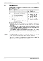
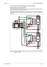
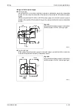
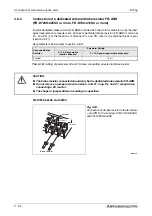
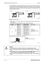
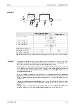
It is recommended to configure a sequence, which shuts off power in the input side of the in-
verter by the external thermal relay as shown below, to prevent overheat and burnout of the high
duty brake resistor in case the regenerative brake transistor is damaged. The following figure
shows two connection examples (circuits). (The brake resistor can not be connected to the
FR-D720S-008SC or 014SC.)
Refer to Tab. 3-19 for the type number of each capacity of thermal relay and the diagram for
the connection.
When the power supply is 400V class, install a step-down transformer.
I002043E
Fig. 3-27:
Protection circuits
Power Supply
Voltage
Type
High-duty Brake
Resistor
Thermal Relay Type
(Mitsubishi Product)
Contact Rating
230V
FR-ABR
FR-ABR-0.4K
TH-N20CXHZKP-0.7A
110V AC/5A
220V AC/2A (AC 11 class),
110V DC/0.5A
220V DC/0.25A (DC 11 class)
FR-ABR-0.75K
TH-N20CXHZKP-1.3A
FR-ABR-1.5K
TH-N20CXHZKP-2.1A
400V
FR-ABR-H0.4K
TH-N20CXHZKP-0.24A
FR-ABR-H0.75K
TH-N20CXHZKP-0.35A
FR-ABR-H1.5K
TH-N20CXHZKP-0.9A
FR-ABR-H2.2K
TH-N20CXHZKP-1.3A
FR-ABR-H3.7K
TH-N20CXHZKP-2.1A
FR-ABR-H5.5K
TH-N20CXHZKP-2.5A
FR-ABR-H7.5K
TH-N20CXHZKP-3.6A
Tab. 3-19:
Resistor and thermal relay combination
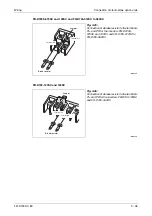
Fig. 3-28:
Connecting the thermal relay
I001458E
b
CAUTION:
●
The brake resistor connected should only be the dedicated brake resistor.
●
Perform wiring and operation according to the Instruction Manual of each option
unit.
●
Brake resistor can not be used with the brake unit (FR-BU2), high power factor
converter (FR-HC), power supply regeneration converter (FR-CV), etc.
●
Do not connect a resistor directly to the DC terminals P/+ and N/–. This could cause
a fire.
Power
supply
Inverter
Thermo relay
(OCR)
OFF
ON
Example 1
Brake
restistor
Inverter
OFF
ON
Example 2
Brake
restistor
OCR
contact
Power
supply
Thermo relay
(OCR)
OCR
contact
T
T
To the inverter
P/+ terminal
To a resistor
Summary of Contents for FR-D720S SC EC
Page 2: ......
Page 4: ......
Page 24: ...Description of the case Product checking and part identification 1 4 ...
Page 108: ...Operation panel Operation 4 20 ...
Page 436: ...Setting for the parameter unit and operation panel Parameter 6 286 ...
Page 484: ...Measurements on the main circuit Maintenance and inspection 8 14 ...
Page 504: ...Specification change Appendix A 20 ...
Page 505: ......
Page 506: ......
Page 510: ...Index Appendix A 24 ...
Page 511: ......

