Selection and protection of a motor
Parameter
6 - 70
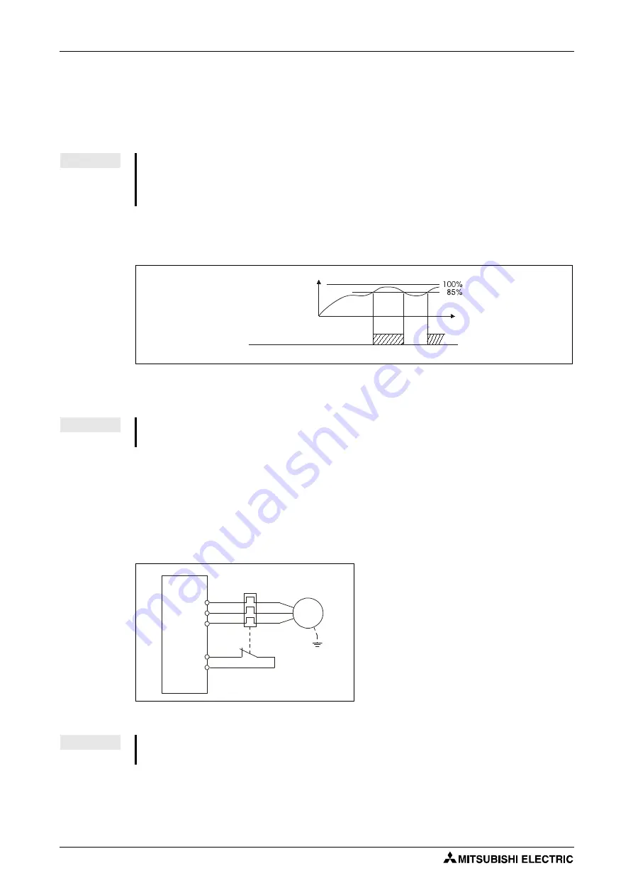
Electronic thermal relay function prealarm (TH) and alarm signal (THP signal)
The alarm signal (THP) is output and electronic thermal relay function prealarm (TH) is dis-
played when the electronic thermal O/L relay cumulative value reaches 85% of the level set in
Pr. 9 or Pr. 51. If it reaches 100% of the Pr. 9 "Electronic thermal O/L relay setting", a motor over-
load trip (E.THM) occurs.
The frequency inverter output is not switched off if the prealarm signal is triggered. For the ter-
minal used for the THP signal output, assign the function by setting "8 (positive logic) or 108
(negative logic)" in any of Pr. 190, Pr. 192 or Pr. 197.
External thermal relay input (OH signal)
To protect the motor against overheat, use the OH signal (refer to Fig. 6-36) when using an ex-
ternal thermal relay or the built-in thermal protector of the motor.
When the thermal relay operates, the inverter trips and outputs the fault signal (E.OHT).
For the terminal used for OH signal input, assign the function by setting "7" to any of Pr. 178 to
Pr. 182 "Input terminal function selection".
NOTE
The prealarm signal "THP" is also issued as soon as the thermal load of the IGBT output
stages of the frequency inverter is 85%. If the load rises further up to 100%, then the thermal
overload protection of the frequency inverter responds and the "E.THT" error message is
shown.
I001138E
Fig. 6-35:
Prealarm signal output
NOTE
Changing the terminal assignment using Pr. 190, Pr. 192 or Pr. 197 may affect the other
functions. Make setting after confirming the function of each terminal.
Fig. 6-36:
Connection of an external thermal relay
I000553C
NOTE
Changing the terminal assignment using Pr. 178 to Pr. 182 may affect the other functions.
Make setting after confirming the function of each terminal.
Electronic thermal relay function
operation level
Time
ON
ON
Electronic thermal O/L relay prealarm THP
U
V
W
M
3
~
OH
PC
Summary of Contents for FR-D720S SC EC
Page 2: ......
Page 4: ......
Page 24: ...Description of the case Product checking and part identification 1 4 ...
Page 108: ...Operation panel Operation 4 20 ...
Page 436: ...Setting for the parameter unit and operation panel Parameter 6 286 ...
Page 484: ...Measurements on the main circuit Maintenance and inspection 8 14 ...
Page 504: ...Specification change Appendix A 20 ...
Page 505: ......
Page 506: ......
Page 510: ...Index Appendix A 24 ...
Page 511: ......


