


Parameter
Special operation
FR-D700 SC EC
6 - 249
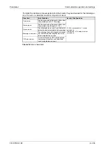
When the X14 signal is not assigned, only the Pr. 128 setting makes PID control valid.
The half-tone screened areas indicate the parameter initial values.
When "100" or larger value is set to any of Pr. 190, Pr. 192 or Pr. 197, the terminal output
has negative logic. (Refer to section 6.9.5 for details.)
If Pr. 133 is used for the set point signal (setting
≠
9999) any additional set point signal
applied to terminals 2-5 will be ignored.
When Pr. 561
≠
9999), terminal 2 is not available for set point input. Use Pr. 133 for set point
input.
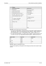
Signal
Terminal
used
Function
Description
Parameter Setting
Output
FUP
Depending
on Pr. 190/
192/197
Upper limit
output
Output to indicate that the meas-
ured value signal exceeded the
upper limit value (Pr. 131).
Pr. 128 = 20, 21
Pr. 131
≠
9999
Set "15" or "115" to any of
Pr. 190, Pr. 192 or Pr. 197.
FDN
Lower limit
output
Output when the measured value
signal falls below the lower limit
(Pr.132).
Pr. 128 = 20, 21
Pr. 132
≠
9999
Set "14" or "114" to any of
Pr. 190, Pr. 192 or Pr. 197.
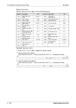
RL
Forward
(reverse)
rotation
direction
output
"Hi" is output to indicate that the
output indication of the parameter
unit is forward rotation (FWD) or
"Low" to indicate that it is reverse
rotation (REV) or stop (STOP).
Set "16" or "116" to any of
Pr. 190, Pr. 192 or Pr. 197.
PID
During PID
control
activated
Turns on during PID control.
Set "47" or "147" to any of
Pr. 190, Pr. 192 or Pr. 197.
SLEEP
PID output
interruption
Turns ON when the PID output
interruption function is performed.
Pr. 575
≠
9999
Set "70" or "170" to any of
Pr. 190, 192 or Pr. 197.
SE
SE
Output
terminal
common
Common terminal for open
collector output terminal.
Tab. 6-88:
I/O signals and parameter settings (2)
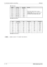
NOTES
Changing the terminal function using any of Pr. 178 to Pr. 182, Pr. 190, Pr. 192 or Pr. 197
may affect the other functions. Make setting after confirming the function of each terminal.
When the Pr. 267 setting was changed, check the voltage/current input switch setting. Differ-
ent setting may cause a fault, failure or malfunction. (Refer to page 6-148 for setting.)
Summary of Contents for FR-D720S SC EC
Page 2: ......
Page 4: ......
Page 24: ...Description of the case Product checking and part identification 1 4 ...
Page 108: ...Operation panel Operation 4 20 ...
Page 436: ...Setting for the parameter unit and operation panel Parameter 6 286 ...
Page 484: ...Measurements on the main circuit Maintenance and inspection 8 14 ...
Page 504: ...Specification change Appendix A 20 ...
Page 505: ......
Page 506: ......
Page 510: ...Index Appendix A 24 ...
Page 511: ......