Precautions for use of the inverter
Operation
4 - 2
●
Do not use the inverter input side magnetic contactor to start/stop the inverter.
Since repeated inrush currents at power ON will shorten the life of the converter circuit
(switching life is about 1,000,000 times), frequent starts and stops of the MC must be
avoided. Always use the start signal (ON/OFF of STF and STR signals) to start/stop the
inverter.
●
Across P/+ and PR terminals, connect only an external regenerative brake discharging
resistor. Do not connect a mechanical brake.
The brake resistor can not be connected to the FR-D720S-008SC and 014SC. Leave
terminals P/+ and PR open. Also, never short between P/+ and PR.
●
Do not apply a voltage higher than the permissible voltage to the inverter I/O signal circuits.
Contact to the inverter I/O signal circuits or opposite polarity may damage the I/O devices.
Especially check the wiring to prevent the speed setting potentiometer from being connected
incorrectly to short terminals 10-5.
●
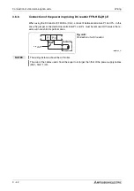
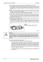
Provide electrical and mechanical interlocks for MC1 and MC2 which are used for commer-
cial power supply-inverterswitch-over.
When the wiring is incorrect or if there is a commercial power supply-inverter switch-over
circuit as shown below, the inverter will be damaged by leakage current from the power
supply due to arcs generated at the time of switch-over or chattering caused by a sequence
error.
●
Inverter input side magnetic contactor (MC)
On the inverter input side, connect an MC for the following purposes:
– To release the inverter from the power supply when a fault occurs or when the drive is
not functioning (e.g. emergency stop operation). For example, MC avoids overheat or
burnout of the brake resistor when heat capacity of the resistor is insufficient or brake
regenerative transistor is damaged with short while connecting an optional brake resistor.
– To prevent any accident due to an automatic restart at restoration of power after an
inverter stop made by a power failure.
– To separate the inverter from the power supply to ensure safe maintenance and
inspection work.
Fig. 4-1:
Mechanical interlocks for MC1 and MC2
I001042E
b
CAUTION:
If the machine must not be restarted when power is restored after a power failure,
provide a magnetic contactor in the inverter's input side and also make up a sequence
which will not switch on the start signal. If the start signal (start switch) remains on
after a power failure, the inverter will automatically restart as soon as the power is
restored.
Power
supply
Undesirable current
M
3~
Summary of Contents for FR-D720S SC EC
Page 2: ......
Page 4: ......
Page 24: ...Description of the case Product checking and part identification 1 4 ...
Page 108: ...Operation panel Operation 4 20 ...
Page 436: ...Setting for the parameter unit and operation panel Parameter 6 286 ...
Page 484: ...Measurements on the main circuit Maintenance and inspection 8 14 ...
Page 504: ...Specification change Appendix A 20 ...
Page 505: ......
Page 506: ......
Page 510: ...Index Appendix A 24 ...
Page 511: ......


