


Position control under vector control
223
5
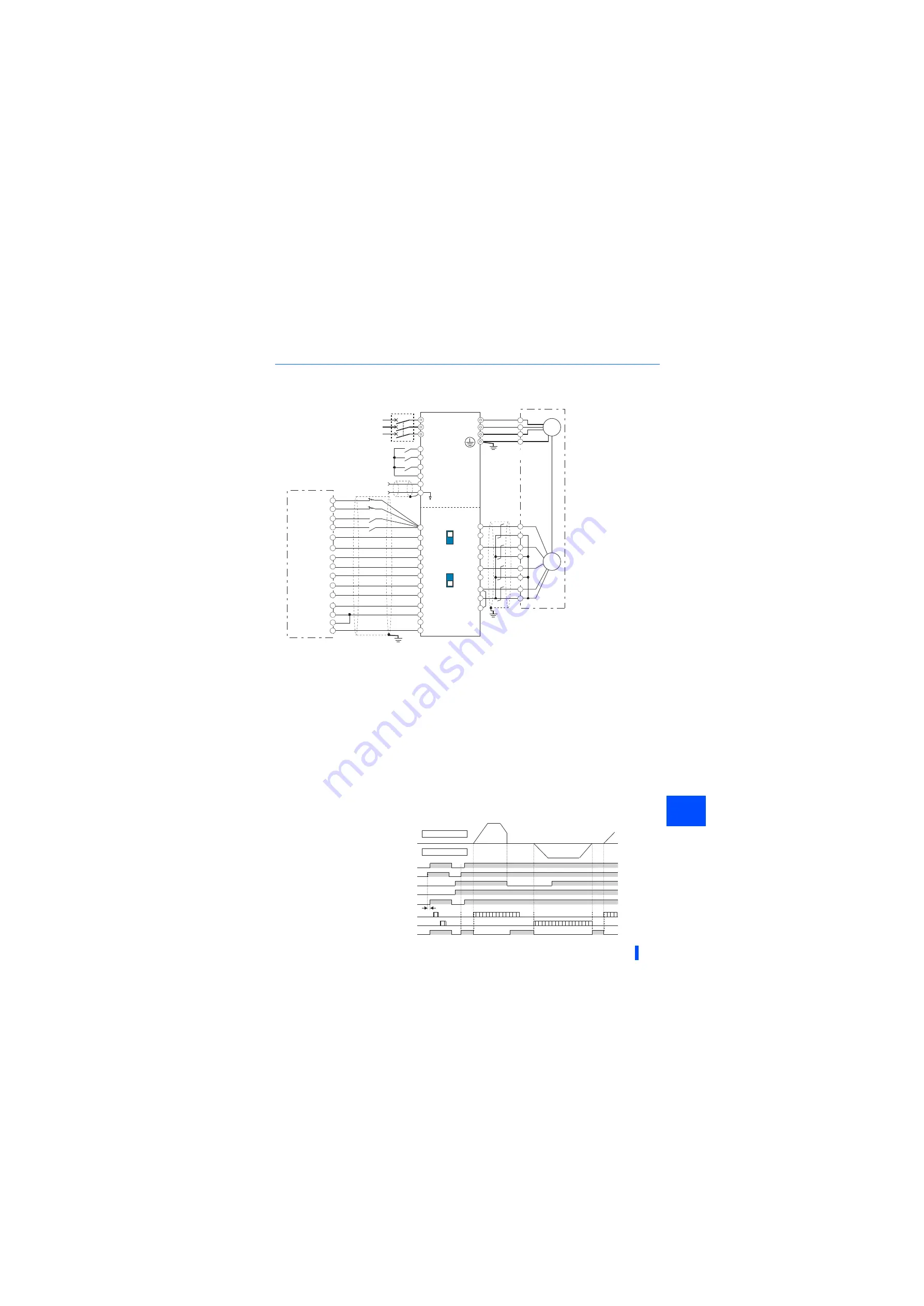
Connection diagram
• Connection with the positioning module of RD75P type MELSEC iQ-R series is also available.
The pin number differs according to the encoder used. Speed control, torque control, and position control by pulse train input are available with
or without the Z-phase being connected.
Connect the encoder so that there is no looseness between the motor and motor shaft. Speed ratio must be 1:1.
Earth (ground) the shield of the encoder cable to the enclosure using a tool such as a P-clip. (Refer to
.)
For the complementary, set the terminating resistor selection switch to the OFF position (initial status). (Refer to
A separate external power supply of 15 V is necessary according to the encoder power specification. When the encoder output is the differential
line driver type, only 5 V can be input. When the 24 V power supply of the FR-A8AL is used, the power is supplied to the encoder through
terminal PG24. When the 5 V/12 V power supply of the FR-A8AL is used, the power is supplied to the encoder through terminal PGV. Do not use
the external power supply simultaneously with the 5 V/12 V power supply or the 24 V power supply. Make the voltage of the external power
supply the same as the encoder output voltage, and connect the external power supply between terminals PG and SD.
Assign the function using
Pr.178 to Pr.184, Pr.187 to Pr.189 (Input terminal function selection)
.
The pulse signal from the position module is available for both open collector and differential line driver. However, the connections are different.
(The following figure shows an example for differential line driver.) For the connection method, refer to the Instruction Manual of the FR-A8AL.
Operation outline
• If the pre-excitation/servo ON (LX) signal is turned ON, output shutoff is canceled and the position control preparation ready
(RDY) signal is turned ON after 0.1 second. When the STF signal (forward stroke end) or the STR signal (reverse stroke
end) is turned ON, the motor rotates according to the command pulse. When the forward (reverse) stroke end signal is
turned OFF, the motor does not rotate in the corresponding direction.
1
5
R/L1
S/L2
T/L3
*7
PA
FR-A8AL
PAR
PB
PBR
PZ
PZR
PG
PG24
SD
STF
STR
LX
CR
CLEAR
PP
PGP
PGN
Vector-control-dedicated motors
U
V
W
U
V
W
E
A
MCCB
B
C
D
F
G
S
R
IM
Positioning module
MELSEQ iQ-R RD75P
PULSE F
CLRCOM
PG024
RDYCOM
READY
NP
PULSE R
SD
SD
VDD
OPC
RDY
VDD
FLS
RLS
DOG
STOP
COM
PG0COM
FPZ2
SD
Complementary
Differential
*4
*1
*2
*3
*6
*5
Terminating
resistor
OFF
ON
Three-phase
AC power
supply
Inverter
Earth
(Ground)
(+)
(-)
Torque limit
command
(
±10V)
Encoder
Forward stroke end
Reverse stroke end
Pre-excitation (servo on)
Actual rotation
Forward rotation
Reverse rotation
Base signal
Position control preparation ready (RDY)
Forward rotation command (STF)
Reverse rotation command (STR)
In-position (Y36)
Servo on (LX)
0.1s
Forward rotation pulse train (PGP/PP)
Reverse rotation pulse train (PGN/NP)
Summary of Contents for 800 Series
Page 11: ...MEMO 10 ...
Page 17: ...MEMO 16 ...
Page 95: ...MEMO 94 ...
Page 671: ...MEMO 670 ...
Page 681: ...MEMO 680 ...