


Chapter 8 Configuring V5.2 European IDLC
Setting Call Control Resource Allocation Values
8-28
255-700-447
PacketStar
®
PSAX 2300 Multiservice Media Gateway User Guide
, Issue 1
Release 9.0.0
Accessing the V5 Interface Variant Configuration Window
Perform the following procedure to create and configure V5 variants.
Begin
1
From the V5 Intf Variant Table select the Add Variant Entry command.
The V5 Interface Variant Configuration window displays (see
Figure 8-10). Table 8-17 describes the commands and Table 8-18
describes the fields on this window.
2
Enter the values as described in Table 8-18 and when completed select
the Apply the Configuration command.
Add Variant Entry
Displays the V5 Interface Variant Configuration
window.
Go Back to Previous screen
Displays the V5 Interface Configuration window.
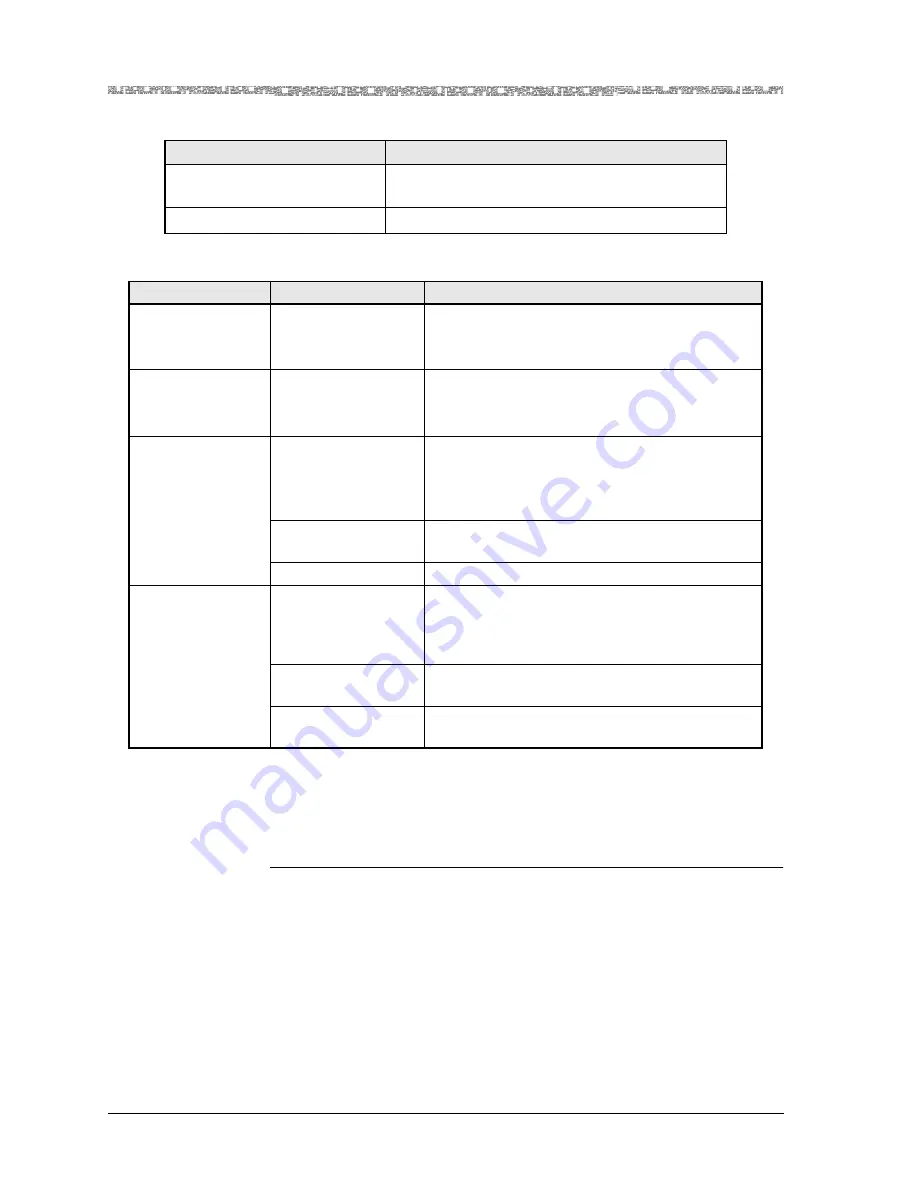
Table 8-15. Commands for the V5 Intf Variant Table Window (Continued)
Command
Function
Table 8-16. Field Descriptions for the V5 Interface Variant Table Window
Field Name
Field Value
Field Description
V5 Intf ID
Default: 0
Range: 1–10
Format: Numeric
Specifies the V5 interface identifier.
V5 Variant ID
Default: 0
Range: 0–127
Format: Numeric
Specifies the V5 variant identifier.
[Admin Status]
(display only)
Default: OutOfSer-
vice
Range: N/A
Format: Predefined
Specifies the Administrative status of the Variant
channel.
OutOfService
Indicates that the variant channel is not in ser-
vice.
InService
Indicates that the variant channel is in service.
[Var Protection Sta-
tus] (display only)
Default: Active
Range: N/A
Format: Predefined
Specifies whether the variant protection status is
active or inactive.The displayed value shows
which variant is active/standby in this particular
V5 interface.
Active
Indicates that this variant is active and opera-
tional.
Passive
Indicates that this variant is not active but in
standby mode.


