Electrical installation
Wiring of system bus (CAN)
81
EDBCSXS064 EN 4.0
5.5
Wiring of system bus (CAN)
Note!
System bus (CAN)
The
ECSxA...
axis module can communicate with a higher−level host system
(PLC) or further controllers via both CAN interfaces (X4 or X14).
MotionBus (CAN)
The "MotionBus (CAN)" term expresses the functionality of the CAN interface
X4 in case of
ECSxS/P/M...
axis modules, where communication takes place
using a higher−level host system (PLC) or further controllers exclusively via the
X4 interface. Interface X14 (CAN−AUX) is exclusively used for parameter setting
and diagnostics.
Basic wiring of the CAN bus networks
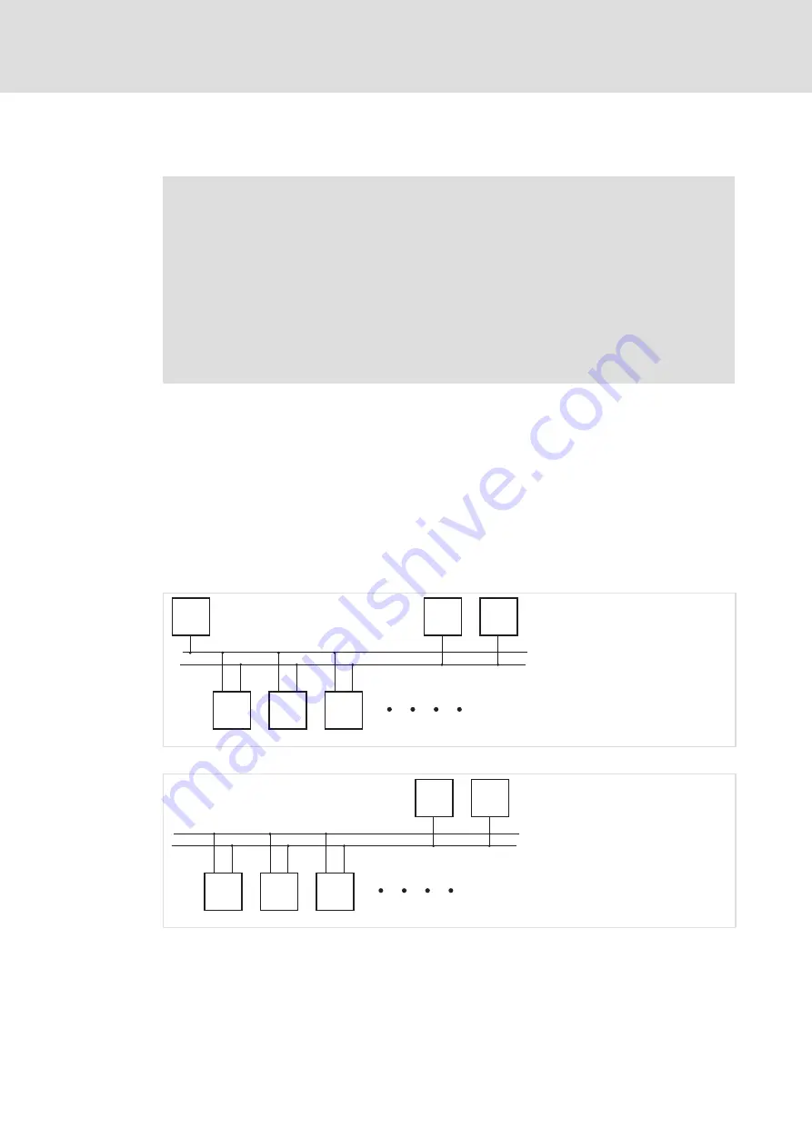
The two following schematic diagrams show drive systems with different master value
concepts:
ƒ
In Fig. 5−14 a higher−level control assumes the function of the master, e.g. ETC.
ƒ
In Fig. 5−15 the function of the master is enabled by a controller intended as master.
In both representations, the master value transmission is effected via the
MotionBus(CAN), interface X4.
The system bus (CAN), interface X14, serves to diagnose and/or parameterise the drives.
PC
M
HMI
S
S
S
X4
X14
X14
X14
X4
X4
MB
SB
ECS_COB006
Fig. 5−14
MotionBus (CAN) with master control
PC
M
HMI
S
S
X4
X14
X14
X14
X4
X4
MB
SB
ECS_COB007
Fig. 5−15
MotionBus (CAN) with controller as master
MB
MotionBus (CAN), interface X4
SB
System bus (CAN), interface X14
M
Master
S
Slave
PC
PC with the Lenze parameter setting and operating software (GDC, GDL, GDO)
HMI
HMI / operating unit


