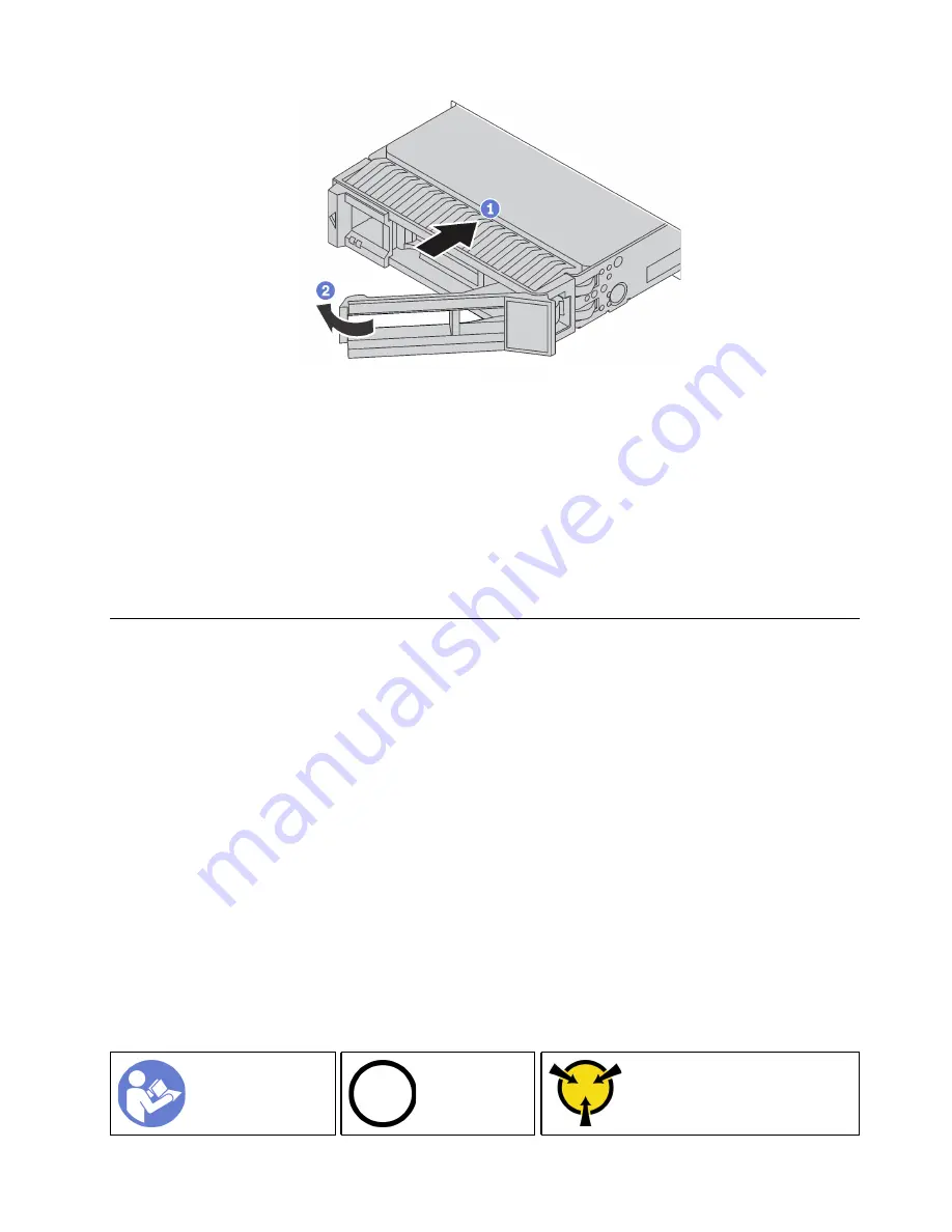
Figure 55. 3.5-inch hot-swap drive installation
Step 1. Ensure that the drive handle is in the open position. Slide the drive into the drive bay until it snaps
into position.
Step 2. Rotate the tray handle to the closed position.
Step 3. Check the hot-swap drive status LED to verify that the hot-swap drive is operating correctly. If the
yellow hot-swap drive status LED of a drive is lit continuously, that drive is faulty and must be
replaced. If the green hot-swap drive activity LED is flashing, the drive is being accessed.
Complete the parts replacement. See “Complete the parts replacement” on page 164.
Simple-swap drive replacement
Use this information to remove and install a simple-swap drive.
Notes:
• The term “simple-swap drive” refers to all the supported types of simple-swap hard disk drives and solid-
state drives.
• Use any documentation that comes with the drive and follow those instructions in addition to the
instructions in this topic. Ensure that you have all the cables and other equipment that are specified in the
documentation that comes with the drive.
• The electromagnetic interference (EMI) integrity and cooling of the server are protected by having all drive
bays covered or occupied. The number of the installed drives in your server varies depending on the
server model. The vacant bays are either covered by an EMI-protective panel or occupied by drive fillers.
When installing a drive, save the removed drive filler in case that you later remove the drive and need the
drive filler to cover the place.
• To avoid damage to the drive connectors, ensure that the top cover is in place and fully closed whenever
you install or remove a drive.
Remove a simple-swap drive
Use this information to remove a simple-swap drive.
Ground package before opening”
.
Hardware replacement procedures
79
Summary of Contents for ThinkSystem SR550
Page 1: ...ThinkSystem SR550 Maintenance Manual Machine Types 7X03 and 7X04 ...
Page 8: ...vi ThinkSystem SR550 Maintenance Manual ...
Page 49: ...Chapter 2 Server components 41 ...
Page 60: ...52 ThinkSystem SR550 Maintenance Manual ...
Page 113: ...Figure 80 Riser 1 assembly removal Chapter 3 Hardware replacement procedures 105 ...
Page 174: ...166 ThinkSystem SR550 Maintenance Manual ...
Page 192: ...184 ThinkSystem SR550 Maintenance Manual ...
Page 196: ...188 ThinkSystem SR550 Maintenance Manual ...
Page 200: ...192 ThinkSystem SR550 Maintenance Manual ...
Page 205: ......
Page 206: ......


