PS200 Configuration & Operation Guide
OPTIONS & FEATURES
Page 91
Setpoints, System Curve Compensation
The PS200 system can automatically compensate for system friction losses due to increased flow in single pump
operation or multi-pump backup modes. Tables are available in most pump catalogs to assist in determining the
amount of friction loss that can be expected for various pipe sizes and flow rates on simple systems.
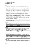
The diagram below illustrates a typical system curve in relation to pump speed.
Constant Pressure Line
Pressure Increase
Res
ulti
ng
Sys
tem
Cur
ve C
om
pen
sati
on
System Curve
Set
Pressure
Head /
Pressure
Flow
N=100
%
%N
%N
%N
%N
0
In this case the system pressure setpoint is shown at shutoff and the increase in setpoint pressure is shown for
increasing flow.
EXAMPLE - If the setpoint is 150 Ft [65 PSIG @ 1.0 SG] and the system resistance increase 10 Ft at the maximum
flow rate, or roughly 7% of the setpoint, parameter 21.08 would be set as "7"
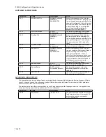
Parameter
Name
Value/Range
Notes
21.09
PRESS INCR SPEED
0-3600 RPM
1200 RPM
[default]
This is the speed at which system curve
compensation begins. At speeds below
this, no compensation for increased
resistance is made.
21.10
PRESS INCR %
0-100%
0%
[default]
This is the amount that PumpSmart will
have increased the setpoint at maximum
speed.
Summary of Contents for PumpSmart PS200
Page 1: ... PUMPSMART CONTROL SOLUTIONS PS200 Version 4 0 Configuration Operation Guide ...
Page 2: ......
Page 4: ......
Page 8: ......
Page 26: ......
Page 72: ......
Page 105: ......
Page 119: ......
Page 146: ...PS200 Configuration Operation Guide APPENDIX A 3 PARAMETER LISTING Page 143 ...
Page 147: ......
Page 158: ......


