PS200 Configuration & Operation Guide
APPENDIX A-1 KEYPAD USE
Page 106
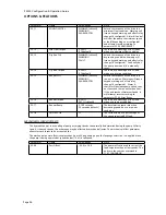
Table 3 – Changing the displayed signals
Step
Function/Description
Key Sequence
Display after key is pressed
1
Press the ACT key to enter the Actual
Signal display mode
ACT
1 L
Æ
0.0 RPM 0
FLOW ACTUAL 0.0 GPM
PUMP SPEED 0.0 RPM
FLOW REF 0.0 GPM
2
Using the arrow keys, move the blinking
cursor to the line that is to changed
OR
1 L
Æ
0.0 RPM 0
FLOW ACTUAL 0.0 GPM
PUMP SPEED 0.0 RPM
FLOW REF 0.0 GPM
3
Press the ENTER key to enter the
ACTUAL SIGNALS parameter groups.
ENTER
1 L
Æ
0.0 RPM 0
1 VFD ACTUAL SIGNALS
02 MOTOR SPEED
0.0 RPM
4
Press the double arrow key to toggle
between parameter group 01 VFD
ACTUAL SIGNALS and group 02 PUMP
ACTUAL SIGNALS
OR
1 L
Æ
0.0 RPM 0
2 PUMP ACTUAL SIGNALS
01 FLOW REF
0.0 GPM
5
Use the arrow keys to scroll through the
available selections.
OR
1 L
Æ
0.0 RPM 0
2 PUMP ACTUAL SIGNALS
12 ENERGY SAVINGS
0.00 $
6
Press and hold ENTER to accept the
selection. Display will revert back to the
normal display mode with selected
parameter shown.
ENTER
1 L
Æ
0.0 rpm 0
Flow Actual 0.0 GPM
Pump speed 0.0 RPM
Energy Savings $0.00
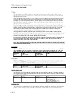
NOTE - When parameter changes are made that will affect the ACTUAL SIGNAL display (e.g. unit changes), pressing the
ACT key will update the display.
Summary of Contents for PumpSmart PS200
Page 1: ... PUMPSMART CONTROL SOLUTIONS PS200 Version 4 0 Configuration Operation Guide ...
Page 2: ......
Page 4: ......
Page 8: ......
Page 26: ......
Page 72: ......
Page 105: ......
Page 119: ......
Page 146: ...PS200 Configuration Operation Guide APPENDIX A 3 PARAMETER LISTING Page 143 ...
Page 147: ......
Page 158: ......


