GLOSSARY
Glossary-7
GL
OS
S
A
R
Y
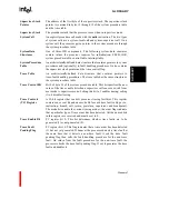
Supervisor Stack
Pointer
The address of the first byte of the supervisor stack. The supervisor stack
pointer is contained in bytes 12 through 15 of the system procedure table
and the trace table.
Supervisor Stack
The procedure stack that the processor uses when in supervisor mode.
System Call
An explicit procedure call made with the
calls
instruction. The two types
of system calls are a system-local call and system-supervisor call. On a
system call, the processor gets a pointer to the system procedure through
the system procedure table.
System Data
Structures
One of three IMI components. The following system data structures
contain values the processor requires for initialization: PRCB, IBR,
system procedure table, control table, interrupt table.
System Procedure
Table
An architecturally-defined data structure that contains pointers to system
procedures and (optionally) to fault handling procedures. It also contains
the supervisor stack pointer and the trace control flag.
Trace Table
An architecturally-defined data structure that contains pointers to
trace-fault-handling procedures. The trace table has the same structure as
the system procedure table.
Trace Control Bit
Bit 0 of byte 12 of the system procedure table. This bit specifies the new
value of the trace enable bit when a supervisor call causes a switch from
user mode to supervisor mode. Setting this bit to 1 enables tracing; setting
it to 0 disables tracing.
Trace Controls
(TC) Register
A 32-bit register that controls processor tracing facilities. This register
contains one event bit and one mode bit for each trace fault subtype (i.e.,
instruction, branch, call, return, prereturn, supervisor and breakpoint).
The mode bits enable the various tracing modes; the event flags indicate
that a particular type of trace event has been detected. All the unused bits
in this register are reserved and must be set to 0.
Trace Enable Bit
PC register bit 0. This bit determines whether trace faults are to be
generated (1) or not generated (0).
Trace Fault
Pending Flag
PC register bit 10. This flag indicates that a trace event has been detected
(1) but not yet generated. Whenever the processor detects a trace fault at
the same time that it detects a non-trace fault, it sets the trace fault
pending flag then calls the fault handling procedure for the non-trace
fault. On return from the fault procedure for the non-trace fault, the
processor checks the trace fault pending flag. If set, it generates the trace
fault and handles it.
Summary of Contents for i960 Jx
Page 1: ...Release Date December 1997 Order Number 272483 002 i960 Jx Microprocessor Developer s Manual ...
Page 24: ......
Page 25: ...1 INTRODUCTION ...
Page 26: ......
Page 35: ...2 DATA TYPES AND MEMORY ADDRESSING MODES ...
Page 36: ......
Page 46: ......
Page 47: ...3 PROGRAMMING ENVIRONMENT ...
Page 48: ......
Page 73: ...4 CACHE AND ON CHIP DATA RAM ...
Page 74: ......
Page 85: ...5 INSTRUCTION SET OVERVIEW ...
Page 86: ......
Page 111: ...6 INSTRUCTION SET REFERENCE ...
Page 112: ......
Page 233: ...7 PROCEDURE CALLS ...
Page 234: ......
Page 256: ......
Page 257: ...8 FAULTS ...
Page 258: ......
Page 291: ...9 TRACING AND DEBUGGING ...
Page 292: ......
Page 309: ...10 TIMERS ...
Page 310: ......
Page 324: ......
Page 325: ...11 INTERRUPTS ...
Page 326: ......
Page 369: ...12 INITIALIZATION AND SYSTEM REQUIREMENTS ...
Page 370: ......
Page 412: ......
Page 413: ...13 MEMORY CONFIGURATION ...
Page 414: ......
Page 429: ...14 EXTERNAL BUS ...
Page 430: ......
Page 468: ......
Page 469: ...15 TEST FEATURES ...
Page 470: ......
Page 493: ...A CONSIDERATIONS FOR WRITING PORTABLE CODE ...
Page 494: ......
Page 502: ......
Page 503: ...B OPCODES AND EXECUTION TIMES ...
Page 504: ......
Page 515: ...C MACHINE LEVEL INSTRUCTION FORMATS ...
Page 516: ......
Page 523: ...D REGISTER AND DATA STRUCTURES ...
Page 524: ......
Page 550: ......
Page 551: ...GLOSSARY ...
Page 552: ......
Page 561: ...INDEX ...
Page 562: ......
Page 578: ......


