


TIMERS
10-4
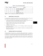
10.1.1.1
Bit 0 - Terminal Count Status Bit (TMRx.tc)
The TMRx.tc bit is set when the Timer Count Register (TCRx) decrements to 0 and bit 2
(TMRx.reload) is not set for a timer. The TMRx.tc bit allows applications to monitor timer status
through software instead of interrupts. TMRx.tc remains set until software accesses (reads or
writes) the TMRx. The access clears TMRx.tc. The timer ignores any value specified for TMRx.tc
in a write request.
When auto-reload is selected for a timer and the timer is enabled, the TMRx.tc bit status is
unpredictable. Software should not rely on the value of the TMRx.tc bit when auto-reload is
enabled.
The processor also clears the TMRx.tc bit upon hardware or software reset. Refer to
section 12.2,
“INITIALIZATION” (pg. 12-2)
.
10.1.1.2
Bit 1 - Timer Enable (TMRx.enable)
The TMRx.enable bit allows user software to control the timer’s RUN/STOP status. When:
TMRx.enable = 1
The Timer Count Register (TCRx) value decrements every Timer Clock
(TCLOCK) cycle. TCLOCK is determined by the Timer Input Clock Select
(TMRx.csel bits 0-1). See
section 10.1.1.5
. When TMRx.reload=0, the
timer automatically clears TMRx.enable when the count reaches zero.
When TMRx.reload=1, the bit remains set. See
section 10.1.1.3
.
TMRx.enable = 0
The timer is disabled and ignores all input transitions.
User software sets this bit. Once started, the timer continues to run, regardless of other processor
activity.For example, the timer runs while the processor is in Halt mode. Three events can stop the timer:
•
User software explicitly clearing this bit (i.e., TMRx.enable = 0).
•
TCRx value decrements to 0, and the Timer Auto Reload Enable (TMRx.reload) bit = 0.
•
Hardware or software reset. Refer to
section 12.2, “INITIALIZATION” (pg. 12-2)
.
Summary of Contents for i960 Jx
Page 1: ...Release Date December 1997 Order Number 272483 002 i960 Jx Microprocessor Developer s Manual ...
Page 24: ......
Page 25: ...1 INTRODUCTION ...
Page 26: ......
Page 35: ...2 DATA TYPES AND MEMORY ADDRESSING MODES ...
Page 36: ......
Page 46: ......
Page 47: ...3 PROGRAMMING ENVIRONMENT ...
Page 48: ......
Page 73: ...4 CACHE AND ON CHIP DATA RAM ...
Page 74: ......
Page 85: ...5 INSTRUCTION SET OVERVIEW ...
Page 86: ......
Page 111: ...6 INSTRUCTION SET REFERENCE ...
Page 112: ......
Page 233: ...7 PROCEDURE CALLS ...
Page 234: ......
Page 256: ......
Page 257: ...8 FAULTS ...
Page 258: ......
Page 291: ...9 TRACING AND DEBUGGING ...
Page 292: ......
Page 309: ...10 TIMERS ...
Page 310: ......
Page 324: ......
Page 325: ...11 INTERRUPTS ...
Page 326: ......
Page 369: ...12 INITIALIZATION AND SYSTEM REQUIREMENTS ...
Page 370: ......
Page 412: ......
Page 413: ...13 MEMORY CONFIGURATION ...
Page 414: ......
Page 429: ...14 EXTERNAL BUS ...
Page 430: ......
Page 468: ......
Page 469: ...15 TEST FEATURES ...
Page 470: ......
Page 493: ...A CONSIDERATIONS FOR WRITING PORTABLE CODE ...
Page 494: ......
Page 502: ......
Page 503: ...B OPCODES AND EXECUTION TIMES ...
Page 504: ......
Page 515: ...C MACHINE LEVEL INSTRUCTION FORMATS ...
Page 516: ......
Page 523: ...D REGISTER AND DATA STRUCTURES ...
Page 524: ......
Page 550: ......
Page 551: ...GLOSSARY ...
Page 552: ......
Page 561: ...INDEX ...
Page 562: ......
Page 578: ......