PROCEDURE CALLS
7-4
7.1.2
Local Register and Stack Management
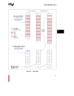
Global register g15 (FP) and local registers r0 (PFP), r1 (SP) and r2 (RIP) contain information to
link procedures together and link local registers to the procedure stack (
Figure 7-1
). The following
subsections describe this linkage information.
7.1.2.1
Frame Pointer
The frame pointer is the current stack frame’s first byte address. It is stored in global register g15,
the frame pointer (FP) register. The FP register is always reserved for the frame pointer; do not use
g15 for general storage.
Stack frame alignment is defined for each implementation of the i960 processor family, according
to an SALIGN parameter (see
section A.3, “Data and Data Structure Alignment” (pg. A-3)
). In the
i960 Jx processor, stacks are aligned on 16-byte boundaries (see
Figure 7-1
). When the processor
needs to create a new frame on a procedure call, it adds a padding area to the stack so that the new
frame starts on a 16-byte boundary.
7.1.2.2
Stack Pointer
The stack pointer is the byte-aligned address of the stack frame’s next unused byte. The stack
pointer value is stored in local register r1, the stack pointer (SP) register. The procedure stack
grows upward (i.e., toward higher addresses). When a stack frame is created, the processor
automatically adds 64 to the frame pointer value and stores the result in the SP register. This action
creates the register save area in the stack frame for the local registers.
The program must modify the SP register value when data is stored or removed from the stack.
The i960 architecture does not provide an explicit push or pop instruction to perform this action.
This is typically done by adding the size of all pushes to the stack in one operation.
7.1.2.3
Considerations When Pushing Data onto the Stack
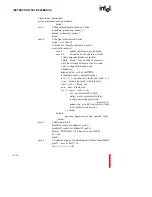
Care should be taken in writing to the stack in the presence of unforeseen faults and interrupts. In
the general case, to ensure that the data written to the stack is not corrupted by a fault or interrupt
record, the SP should be incremented first to allocate the space, and then the data should be written
to the allocated space:
mov
sp,r4
addo
24,sp,sp
st
data,(r4)
...
st
data,20(r4)
Summary of Contents for i960 Jx
Page 1: ...Release Date December 1997 Order Number 272483 002 i960 Jx Microprocessor Developer s Manual ...
Page 24: ......
Page 25: ...1 INTRODUCTION ...
Page 26: ......
Page 35: ...2 DATA TYPES AND MEMORY ADDRESSING MODES ...
Page 36: ......
Page 46: ......
Page 47: ...3 PROGRAMMING ENVIRONMENT ...
Page 48: ......
Page 73: ...4 CACHE AND ON CHIP DATA RAM ...
Page 74: ......
Page 85: ...5 INSTRUCTION SET OVERVIEW ...
Page 86: ......
Page 111: ...6 INSTRUCTION SET REFERENCE ...
Page 112: ......
Page 233: ...7 PROCEDURE CALLS ...
Page 234: ......
Page 256: ......
Page 257: ...8 FAULTS ...
Page 258: ......
Page 291: ...9 TRACING AND DEBUGGING ...
Page 292: ......
Page 309: ...10 TIMERS ...
Page 310: ......
Page 324: ......
Page 325: ...11 INTERRUPTS ...
Page 326: ......
Page 369: ...12 INITIALIZATION AND SYSTEM REQUIREMENTS ...
Page 370: ......
Page 412: ......
Page 413: ...13 MEMORY CONFIGURATION ...
Page 414: ......
Page 429: ...14 EXTERNAL BUS ...
Page 430: ......
Page 468: ......
Page 469: ...15 TEST FEATURES ...
Page 470: ......
Page 493: ...A CONSIDERATIONS FOR WRITING PORTABLE CODE ...
Page 494: ......
Page 502: ......
Page 503: ...B OPCODES AND EXECUTION TIMES ...
Page 504: ......
Page 515: ...C MACHINE LEVEL INSTRUCTION FORMATS ...
Page 516: ......
Page 523: ...D REGISTER AND DATA STRUCTURES ...
Page 524: ......
Page 550: ......
Page 551: ...GLOSSARY ...
Page 552: ......
Page 561: ...INDEX ...
Page 562: ......
Page 578: ......

