


D-1
D
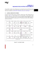
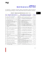
APPENDIX D
REGISTER AND DATA STRUCTURES
This appendix is a compilation of all register and data structure figures described throughout the
manual. Following each figure is a reference that indicates 23the section that discusses the figure.
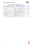
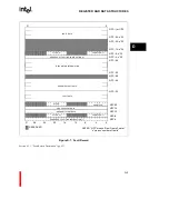
Table D-1. Register and Data Structures (Sheet 1 of 2)
Fig.
Register / Data Structure
Where Defined in the manual
Page
D-1
AC (Arithmetic Controls) Register
Section 3.7.2, “Arithmetic Controls (AC) Register”
(pg. 3-18)
D-3
D-2
PC (Process Controls) Register
Section 3.7.3, “Process Controls (PC) Register” (pg. 3-21)
D-4
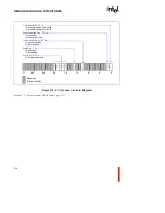
D-3
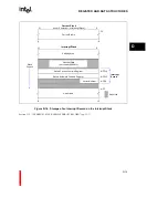
Procedure Stack Structure and Local Registers
Section 7.1.1, “Local Registers and the Procedure Stack”
(pg. 7-2)
D-5
D-4
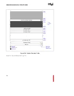
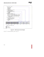
System Procedure Table
Section 7.5.1, “System Procedure Table” (pg. 7-15)
D-6
D-5
PFP (Previous Frame Pointer) Register (r0)
Section 7.8, “RETURNS” (pg. 7-20)
D-7
D-6
Fault Table and Fault Table Entries
Section 8.3, “FAULT TABLE” (pg. 8-4)
D-8
D-7
Fault Record
Section 8.5, “FAULT RECORD” (pg. 8-6)
D-9
D-8
TC (Trace Controls) Register
Section 9.1.1, “Trace Controls (TC) Register” (pg. 9-2)
D-10
D-9
BPCON (Breakpoint Control) Register
section 9.2.7.4, “Breakpoint Control Register” (pg. 9-7)
D-10
D-10
DAB (Data Address Breakpoint) Register
Format
Section 9.2.7.5, “Data Address Breakpoint (DAB) Registers”
(pg. 9-9)
D-11
D-11
IPB (Instruction Breakpoint) Register Format
Section 9.2.7.6, “Instruction Breakpoint (IPB) Registers”
(pg. 9-10)
D-11
D-12
TMR0-1 (Timer Mode Register)
Section 10.1.1, “Timer Mode Registers (TMR0, TMR1)”
(pg. 10-3)
D-12
D-13
TCR0-1 (Timer Count Register)
Section 10.1.2, “Timer Count Register (TCR0, TCR1)”
(pg. 10-6)
D-12
D-14
TRR0-1 (Timer Reload Register)
Section 10.1.3, “Timer Reload Register (TRR0, TRR1)”
(pg. 10-7)
D-13
D-15
Interrupt Table
Section 11.4, “INTERRUPT TABLE” (pg. 11-4)
D-14
D-16
Storage of an Interrupt Record on the Interrupt
Stack
Section 11.5, “INTERRUPT STACK AND INTERRUPT
RECORD” (pg. 11-7)
D-15
D-17
ICON (Interrupt Control) Register
Section 11.7.4, “Interrupt Control Register (ICON)”
(pg. 11-22)
D-16
D-18
IMAP0-IMAP2 (Interrupt Mapping) Registers
Section 11.7.5, “Interrupt Mapping Registers
(IMAP0-IMAP2)” (pg. 11-23)
D-17
D-19
IMSK (Interrupt Mask) Registers
Section 11.7.5.1, “Interrupt Mask (IMSK) and Interrupt
Pending (IPND) Registers” (pg. 11-25)
D-18
D-20
Interrupt Pending (IPND) Register
Section 11.7.5.1, “Interrupt Mask (IMSK) and Interrupt
Pending (IPND) Registers” (pg. 11-25)
D-19
D-21
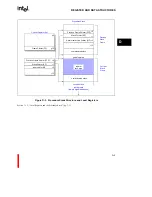
Initial Memory Image (IMI) and Process
Control Block (PRCB)
Section 12.3.1, “Initial Memory Image (IMI)” (pg. 12-10)
D-20
Summary of Contents for i960 Jx
Page 1: ...Release Date December 1997 Order Number 272483 002 i960 Jx Microprocessor Developer s Manual ...
Page 24: ......
Page 25: ...1 INTRODUCTION ...
Page 26: ......
Page 35: ...2 DATA TYPES AND MEMORY ADDRESSING MODES ...
Page 36: ......
Page 46: ......
Page 47: ...3 PROGRAMMING ENVIRONMENT ...
Page 48: ......
Page 73: ...4 CACHE AND ON CHIP DATA RAM ...
Page 74: ......
Page 85: ...5 INSTRUCTION SET OVERVIEW ...
Page 86: ......
Page 111: ...6 INSTRUCTION SET REFERENCE ...
Page 112: ......
Page 233: ...7 PROCEDURE CALLS ...
Page 234: ......
Page 256: ......
Page 257: ...8 FAULTS ...
Page 258: ......
Page 291: ...9 TRACING AND DEBUGGING ...
Page 292: ......
Page 309: ...10 TIMERS ...
Page 310: ......
Page 324: ......
Page 325: ...11 INTERRUPTS ...
Page 326: ......
Page 369: ...12 INITIALIZATION AND SYSTEM REQUIREMENTS ...
Page 370: ......
Page 412: ......
Page 413: ...13 MEMORY CONFIGURATION ...
Page 414: ......
Page 429: ...14 EXTERNAL BUS ...
Page 430: ......
Page 468: ......
Page 469: ...15 TEST FEATURES ...
Page 470: ......
Page 493: ...A CONSIDERATIONS FOR WRITING PORTABLE CODE ...
Page 494: ......
Page 502: ......
Page 503: ...B OPCODES AND EXECUTION TIMES ...
Page 504: ......
Page 515: ...C MACHINE LEVEL INSTRUCTION FORMATS ...
Page 516: ......
Page 523: ...D REGISTER AND DATA STRUCTURES ...
Page 524: ......
Page 550: ......
Page 551: ...GLOSSARY ...
Page 552: ......
Page 561: ...INDEX ...
Page 562: ......
Page 578: ......