6-11
INTERRUPT SYSTEM
time is five states for internal interrupts and six states for external interrupts.
External interrupts must remain active for at least five state times to guarantee
interrupt recognition when the request occurs immediately after a sample has
been taken (i.e., requested in the second half of a sample state time).
If the external interrupt goes active one state after the sample state, the pin is not resampled for
another three states. After the second sample is taken and the interrupt request is recognized, the
interrupt controller requests the context switch. The programmer must also consider the time to
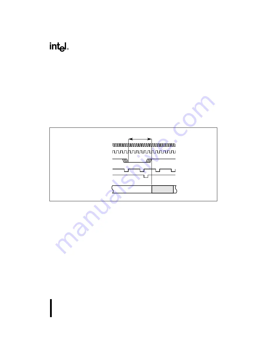
complete the instruction at the moment the context switch request is sent to the execution unit. If
9 states of a 10-state instruction have completed when the context switch is requested, the total
response time is 6 states, with a context switch immediately after the final state of the 10-state
instruction (see Figure 6-6).
Figure 6-6. Response Time Example #1
Conversely, if the external interrupt requests service in the state just prior to the next sample, re-
sponse is much quicker. One state asserts the request, one state samples, and one state requests
the context switch. If at that point the same instruction conditions exist, one additional state time
is needed to complete the 10-state instruction prior to the context switch (see Figure 6-7). The
total response time in this case is four state times. The programmer must evaluate all pertinent
conditions for accurate predictability.
OSC
State Time
INT0#
Sample INT0#
Response Time = 6
Ten State
Instruction
Request
Push PC
A4155-02
Summary of Contents for 8XC251SA
Page 2: ......
Page 3: ...May 1996 8XC251SA 8XC251SB 8XC251SP 8XC251SQ Embedded Microcontroller User s Manual...
Page 18: ......
Page 19: ...1 Guide to This Manual...
Page 20: ......
Page 30: ......
Page 31: ...2 Architectural Overview...
Page 32: ......
Page 41: ...3 Address Spaces...
Page 42: ......
Page 63: ...4 Device Configuration...
Page 64: ......
Page 81: ...5 Programming...
Page 82: ......
Page 102: ......
Page 103: ...6 Interrupt System...
Page 104: ......
Page 120: ......
Page 121: ...7 Input Output Ports...
Page 122: ......
Page 132: ......
Page 133: ...8 Timer Counters and Watchdog Timer...
Page 134: ......
Page 153: ...9 Programmable Counter Array...
Page 154: ......
Page 170: ......
Page 171: ...10 Serial I O Port...
Page 172: ......
Page 187: ...11 Minimum Hardware Setup...
Page 188: ......
Page 197: ...12 Special Operating Modes...
Page 198: ......
Page 206: ......
Page 207: ...13 External Memory Interface...
Page 208: ......
Page 239: ...14 Programming and Verifying Nonvolatile Memory...
Page 240: ......
Page 250: ......
Page 251: ...A Instruction Set Reference...
Page 252: ......
Page 390: ......
Page 391: ...B Signal Descriptions...
Page 392: ......
Page 400: ......
Page 401: ...C Registers...
Page 402: ......
Page 436: ......
Page 437: ...Glossary...
Page 438: ......
Page 446: ......
Page 447: ...Index...
Page 448: ......
Page 458: ......


