v
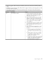
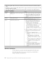
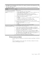
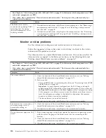
Follow the suggested actions in the order in which they are listed in the Action column until the problem is
solved.
v
See Chapter 4, “Parts listing, Types 8014, 8028 and 1916,” on page 25 to determine which components are CRUs
and which components are FRUs.
v
If an action step is preceded by “(Trained service technician only),” that step must be performed only by a
trained service technician.
Error code
Description
Action
00150700
PERR: Secondary signaled parity error
Slot=
xx
Vendor ID=
xxxx
Device ID=
xxxx
Status=
xxxx
1.
If an optional expansion unit is installed, reseat it
- See “Removing an optional expansion unit” on
page 37 and “Installing an optional expansion
unit” on page 38.
2.
Reseat the I/O expansion card in slot
xx
; then,
restart the blade server.
3.
Replace the following components, one at a time,
in the order shown, restarting the blade server
each time:
a.
I/O expansion card in slot
xx
-
b.
Optional expansion unit (if one is installed) -
See “Removing an optional expansion unit”
on page 37 and “Installing an optional
expansion unit” on page 38.
c.
(Trained service technician only) System-board
assembly - See “Removing the system-board
assembly” on page 65 and “Installing the
system-board assembly” on page 66.
00150900
SERR/PERR Detected on PCI bus (no
source found)
1.
If an optional expansion unit is installed, reseat it
- See “Removing an optional expansion unit” on
page 37 and “Installing an optional expansion
unit” on page 38.
2.
Reseat each I/O expansion card, restarting the
blade server each time.
3.
Replace the following components, one at a time,
in the order shown, restarting the blade server
each time:
a.
I/O expansion card in slot
xx
-
b.
Optional expansion unit (if one is installed) -
See “Removing an optional expansion unit”
on page 37 and “Installing an optional
expansion unit” on page 38.
c.
(Trained service technician only) System-board
assembly - See “Removing the system-board
assembly” on page 65 and “Installing the
system-board assembly” on page 66.
Chapter 6. Diagnostics
107
Summary of Contents for BladeCenter HS12 Type 1916
Page 1: ...BladeCenter HS12 Type 8014 8028 or 1916 Problem Determination and Service Guide...
Page 2: ......
Page 3: ...BladeCenter HS12 Type 8014 8028 or 1916 Problem Determination and Service Guide...
Page 36: ...24 BladeCenter HS12 Type 8014 8028 or 1916 Problem Determination and Service Guide...
Page 186: ...174 BladeCenter HS12 Type 8014 8028 or 1916 Problem Determination and Service Guide...
Page 190: ...178 BladeCenter HS12 Type 8014 8028 or 1916 Problem Determination and Service Guide...
Page 198: ...186 BladeCenter HS12 Type 8014 8028 or 1916 Problem Determination and Service Guide...
Page 203: ......
Page 204: ...Part Number 60Y1601 Printed in USA 1P P N 60Y1601...


