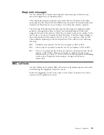
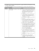
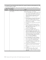
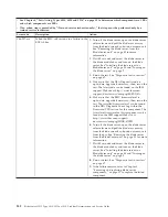
background image

v

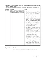
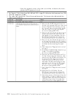
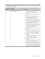
See Chapter 4, “Parts listing, Types 8014, 8028 and 1916,” on page 25 to determine which components are CRUs
and which components are FRUs.

v

If an action step is preceded by “(Trained service technician only),” that step must be performed only by a
trained service technician.

Error code

Description

Action

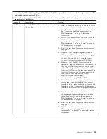
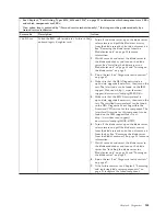
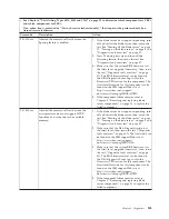
089-801-xxx

Aborted due to an internal program error.

1.

If the blade server has stopped responding, turn
off and restart the blade server. See “Turning off
the blade server” on page 10 and “Turning on
the blade server” on page 9.

2.

Make sure that the DSA Diagnostic code is
up-to-date, upgrade if necessary; then, rerun the
test. The latest code can be found on the IBM
support Web site at http://www.ibm.com/
support/docview.wss?uid=psg1SERV-DSA.

3.

Make sure that the system firmware level is
up-to-date, upgrade if necessary; then, rerun the
test. The installed firmware level can be found
in the DSA Diagnostic Event Log within the
Firmware/VPD section for this component. The
latest level firmware for this component can be
found on the IBM support Web site at
http://www.ibm.com/support/
docview.wss?uid=psg1MIGR-4JTS2T.

4.

If the blade server has stopped responding, turn
off and restart the blade server; then, rerun the
test. See “Turning off the blade server” on page
10 and “Turning on the blade server” on page 9.

5.

(Trained service technician only) If the
component failure remains, refer to Chapter 5,
“Removing and replacing blade server
components,” on page 31 to replace the failed
component.

Chapter 6. Diagnostics

149

Summary of Contents for BladeCenter HS12 Type 1916

Page 1: ...BladeCenter HS12 Type 8014 8028 or 1916 Problem Determination and Service Guide...

Page 2: ......

Page 3: ...BladeCenter HS12 Type 8014 8028 or 1916 Problem Determination and Service Guide...

Page 4: ...s on page 179 and the Warranty and Support Information document for your blade server type on the IBM Documentation CD Seventh Edition May 2010 Copyright IBM Corporation 2008 2010 US Government Users...

Page 5: ...35 Installing the blade server cover 36 Removing an optional expansion unit 37 Installing an optional expansion unit 38 Removing the bezel assembly 39 Installing the bezel assembly 40 Removing a fixe...

Page 6: ...ou call 175 Using the documentation 176 Getting help and information from the World Wide Web 176 Software service and support 176 Hardware service and support 177 IBM Taiwan product service 177 Notice...

Page 7: ...fterne f r du installerer dette produkt Lees voordat u dit product installeert eerst de veiligheidsvoorschriften Ennen kuin asennat t m n tuotteen lue turvaohjeet kohdasta Safety Information Avant d i...

Page 8: ...sed in this section If you identify an unsafe condition you must determine how serious the hazard is and whether you must correct the problem before you work on the product Consider the following cond...

Page 9: ...o not use this type of mat to protect yourself from electrical shock v Do not work alone under hazardous conditions or near equipment that has hazardous voltages v Locate the emergency power off EPO s...

Page 10: ...d with a number This number is used to cross reference an English language caution or danger statement with translated versions of the caution or danger statement in the Safety Information document Fo...

Page 11: ...t and disconnect cables as described in the following table when installing moving or opening covers on this product or attached devices To Connect To Disconnect 1 Turn everything OFF 2 First attach a...

Page 12: ...ce Always replace the blade cover before installing the blade United Kingdom telecommunications safety requirement Notice to Customers This apparatus is approved under approval number NS G 1234 J 1000...

Page 13: ...e problems v Light path diagnostics LEDs See Light path diagnostics LEDs on page 130 for information about light path diagnostics LEDs that are lit and actions that you should take v Event logs See Er...

Page 14: ...stem updates 1 Determine the existing code levels From the advanced management module Web interface click Monitors and then click Firmware VPD In DSA click Firmware VPD to view system firmware levels...

Page 15: ...operating systems or IBM software or devices complete the following steps Note Changes are made periodically to the IBM website The actual procedure might vary slightly from what is described in this...

Page 16: ...blem might not have been previously identified by IBM After you have verified that all code is at the latest level all hardware and software configurations are valid and no light path diagnostics LEDs...

Page 17: ...be installed only by trained service technicians For information about the terms of the warranty and getting service and assistance see the Warranty and Support Information document on the IBM Docume...

Page 18: ...tips guidance or advice v Important These notices provide information or advice that might help you avoid inconvenient or problem situations v Attention These notices indicate possible damage to progr...

Page 19: ...r type 8028 and 1916 v SATA controller type 8014 v Concurrent keyboard video mouse cKVM support when optional cKVM feature card is installed v Light path diagnostics v RS 485 interface for communicati...

Page 20: ...ccupies If there is no response when you press the KVM select button you can use the management module Web interface to determine whether local control has been disabled on the blade server See http w...

Page 21: ...ress this button to associate the shared BladeCenter unit media tray removable media drives with the blade server The LED on the button flashes while the request is being processed and then is lit whe...

Page 22: ...the blade server When you turn off the blade server it is still connected to power through the BladeCenter unit The blade server can respond to requests from the service processor such as a remote re...

Page 23: ...ector locations are identical in the fixed SATA system board Storage interface connector I O expansion option connectors Control panel connector Concurrent KVM connector J149 Expansion unit connector...

Page 24: ...following illustration shows the locations of the two switch blocks SW2 and SW3 and the light path diagnostics switch on the system board The following table describes the function of each switch in...

Page 25: ...ext server start On Enabled Off Disabled default SW3 Switch block 3 is a system reset switch System board LEDs Use this information to locate system board LEDs in the blade server The following illust...

Page 26: ...rocessor error LED Battery error LED Power fault LED The following illustration shows the light path diagnostics panel on the system board NMI SBRD TEMP LP 1 NMI error LED System board error LED Over...

Page 27: ...ng this CD see Using the ServerGuide Setup and Installation CD on page 19 v Preboot Execution Environment PXE boot agent utility program The PXE boot agent utility program is part of the BIOS Use it t...

Page 28: ...ion about the USB devices in the blade server v System Information Select this menu item to view information about the blade server When you make configuration changes through other options in the Con...

Page 29: ...hecks for changes in the boot record when the blade server starts v Advanced Setup Select this menu item to change settings for advanced hardware features Important The blade server might malfunction...

Page 30: ...changes that you have made in the settings and restore the previous settings v Load Default Settings Select this menu item to cancel the changes that you have made in the settings and restore the fac...

Page 31: ...programs that are based on detected hardware v Device drivers that are provided for the blade server model and detected hardware v Operating system partition size and file system type that are selecta...

Page 32: ...e operating system installation program starts You will need the operating system CD to complete the installation 2 The ServerGuide program stores information about the blade server model service proc...

Page 33: ...onds by default to press Ctrl S after the prompt is displayed If the PXE setup prompt is not displayed use the Configuration Setup Utility program to set the Enable Ethernet PXE DHCP option 3 Use the...

Page 34: ...ick Publications lookup 4 From the Product family menu select BladeCenter HS12 and click Continue Configuring a SAS RAID array Use this information to configure a SAS RAID array Configuring a SAS RAID...

Page 35: ...following tasks v Set the SAS device scan order v Set the SAS ID for the controller v Manage the SAS RAID configuration To start the LSI Logic Configuration Utility program complete the following step...

Page 36: ...24 BladeCenter HS12 Type 8014 8028 or 1916 Problem Determination and Service Guide...

Page 37: ...periodically to the IBM Web site The actual procedure might vary slightly from what is described in this document 1 Go to http www ibm com systems support 2 Under Product support click BladeCenter 3 U...

Page 38: ...1 CRU at your request you will be charged for the installation v Tier 2 customer replaceable unit You may install a Tier 2 CRU yourself or request IBM to install it at no additional charge under the...

Page 39: ...dual core type 8028 27x 46C7642 5 Memory 512 MB very low profile VLP ECC DDR2 type 8014 model 1Ax 39M5860 5 Memory 1 GB VLP ECC DDR2 type 8014 model 2Bx type 8028 models 23x 27x 44x 45x 46x 4Lx type 1...

Page 40: ...x EBx 44R5849 Label FRU list type 8014 models 1Ax 2Ax 2Bx EBx 44R5850 Label system service type 8028 models 23x 27x 33x 44x 45x 46x 4Lx 54x 56x E3x type 1916 model 46x 46C1216 Label FRU list type 8028...

Page 41: ...CD Japanese MS Windows Server 2003 R2 32 bit edition 1 2 processors 44W4063 Recovery CD Korean MS Windows Server 2003 R2 32 bit edition 1 2 processors 44W4064 Recovery CD English MS Windows Server 20...

Page 42: ...46C8235 Recovery CD Multilingual MS Windows Server 2008 Enterprise Edition 32Bit 64Bit 1 8 processors 46C8236 Recovery CD Simplified Chinese MS Windows Server 2008 Standard Edition 32Bit 64Bit 1 4 pr...

Page 43: ...ing information v Before you begin read Safety on page v and Installation guidelines This information will help you work safely v When you install your new blade server take the opportunity to downloa...

Page 44: ...ve replace it immediately For instructions see the Problem Determination and Service Guide Handling static sensitive devices Use this information to observe the static sensitive device requirements At...

Page 45: ...ladeCenter unit to install your new blade server remove an existing blade server or filler module from the BladeCenter unit The following illustration shows how to remove a blade server or filler modu...

Page 46: ...BladeCenter unit The following illustration shows how to install a blade server into a BladeCenter unit The appearance of your BladeCenter unit might be different see the documentation for your Blade...

Page 47: ...rver bay number Reinstalling a blade server into a different blade server bay number from the one from which it was removed can have unintended consequences and you might have to reconfigure the blade...

Page 48: ...rom the blade server 6 If you are instructed to return the cover follow all packaging instructions and use any packaging materials for shipping that are supplied to you Installing the blade server cov...

Page 49: ...hat you have not left loose tools or parts inside the blade server 3 Pivot the blade server cover to the closed position until it clicks into place 4 Install the blade server in the BladeCenter unit s...

Page 50: ...es including thumbscrews or levers c Rotate the expansion unit open then lift the expansion unit from the blade server 6 If you are instructed to return the cover or an optional expansion unit follow...

Page 51: ...ver 7 Close the optional expansion unit see the expansion unit documentation for information and instructions v If the optional expansion unit has an extraction device pivot the expansion unit closed...

Page 52: ...the blade server approximately 1 2 cm 0 5 inch 6 Disconnect the control panel cable from the control panel connector 7 Pull the bezel assembly away from the blade server 8 If you are instructed to re...

Page 53: ...ll the cover onto the blade server see Installing the blade server cover on page 36 10 Install the blade server into the BladeCenter unit see Installing the blade server in a BladeCenter unit on page...

Page 54: ...ending on which storage devices you have the blade server machine type 8014 has two storage bays for installing or removing fixed storage devices such as solid state storage drives Note 1 The followin...

Page 55: ...r in a BladeCenter unit on page 34 Removing a hot swap storage drive Use this information to remove a hot swap storage drive The blade server machine type 8028 has two storage bays for installing or r...

Page 56: ...Hot swap storage bay 1 Hot swap storage bay 0 1 Before you begin read Safety on page v and Installation guidelines on page 31 2 Identify the hot swap storage bay hot swap storage bay 0 or hot swap st...

Page 57: ...If an optional expansion unit is installed remove the expansion unit see Removing an optional expansion unit on page 37 DIMM Retaining clip Attention To avoid breaking the retaining clips or damaging...

Page 58: ...server models come with one DIMM installed in DIMM slot 1 In this case you must order and install a second matched DIMM in DIMM slot 2 Install the DIMMs in the order shown in the following table Tabl...

Page 59: ...server from the BladeCenter unit on page 33 for instructions 4 Carefully lay the blade server on a flat static protective surface 5 Open the blade server cover see Removing the blade server cover on p...

Page 60: ...fully seated When the DIMM is correctly installed the retaining clips are parallel to the sides of the DIMM Important If there is a gap between the DIMM and the retaining clips the DIMM has not been...

Page 61: ...sion card on page 50 or Removing a high speed expansion card on page 55 6 Gently pivot the narrow end of the card out of the cKVM card connectors then slide the notched end of the card out of the tabs...

Page 62: ...side of the card that is away from the cKVM connector between the two tabs at the right side of the expansion card bracket then gently pivot the card into the connector Note For device driver and con...

Page 63: ...is installed and you are removing the expansion card from the system board remove the expansion unit see Removing an optional expansion unit on page 37 5 Gently pivot the connectivity card out of the...

Page 64: ...ard All other expansion cards that are installed in other blade servers in the BladeCenter unit must also be compatible with these I O modules In this example you can then install two Ethernet switch...

Page 65: ...in the blade server in step press the card gently so that you do not damage it 11 To correctly seat the I O expansion card in the blade server press down firmly on all four corners of the card The tw...

Page 66: ...expansion unit is installed remove the expansion unit see Removing an optional expansion unit on page 37 5 Gently lift the card out of the expansion card connectors then slide the notched end of the c...

Page 67: ...card connector and press it firmly into place to fully seat the card on the system board 6 If you removed an optional expansion unit reinstall it see Installing an optional expansion unit on page 38...

Page 68: ...then slide the slots at the back end of the card out of the expansion card standoffs and lift the card out of the blade server 6 If you are instructed to return the expansion card follow all packagin...

Page 69: ...then remove the expansion card from the package 7 Orient the expansion card and slide the slots at the back end of the card onto the pins on the expansion card standoff then gently pivot the card into...

Page 70: ...t the battery from the socket 8 Dispose of the battery as required by local ordinances or regulations Installing the battery Use this information to install a battery on the system board in the blade...

Page 71: ...installed in a BladeCenter unit remove it see Removing the blade server from the BladeCenter unit on page 33 for instructions 3 Remove the blade server cover see Removing the blade server cover on pag...

Page 72: ...emain effective if you carefully handle the heat sink and microprocessor when you remove or install these components Do not touch the thermal material or otherwise allow it to become contaminated Note...

Page 73: ...thermal material on the bottom of the heat sink Touching the thermal material will contaminate it If the thermal material on the microprocessor or heat sink becomes contaminated you must replace the...

Page 74: ...tes 1 The microprocessor and heat sink assembly is a field replaceable unit FRU and must be replaced by a trained service technician To contact an IBM service representative see Hardware service and s...

Page 75: ...microprocessor socket from its closed and locked position until it stops in the fully open position approximately a 135 angle as shown b Rotate the microprocessor retainer on the microprocessor socket...

Page 76: ...on the bottom of the heat sink Touching the thermal material will contaminate it If the thermal material on the microprocessor or heat sink becomes contaminated contact your service technician Heat si...

Page 77: ...begin read Safety on page v and Installation guidelines on page 31 2 If the blade server is installed in a BladeCenter unit remove it see Removing the blade server from the BladeCenter unit on page 33...

Page 78: ...talling an I O expansion card on page 51 Installing a storage interface card on page 54 and Installing a high speed expansion card on page 56 v Microprocessors and heat sinks See Installing a micropro...

Page 79: ...eeps indicate a memory error Make sure that all DIMMs are correctly installed For more information see Installing a memory module on page 46 See the Problem Determination and Service Guide for more in...

Page 80: ...e to find the system error logs in the blade server firmware code view the system event log in the BladeCenter management module v Light path diagnostics Use light path diagnostics LEDs on the system...

Page 81: ...roprocessor problems on page 117 for information about diagnosing microprocessor problems v Follow the suggested actions in the order in which they are listed in the Action column until the problem is...

Page 82: ...stems support 2 Reseat the DIMMs See Removing a memory module on page 44 and Installing a memory module on page 46 3 Replace the following components one at a time in the order shown restarting the bl...

Page 83: ...page 46 b Trained service technician only System board assembly See Removing the system board assembly on page 65 and Installing the system board assembly on page 66 c Optional expansion unit if one i...

Page 84: ...the system board assembly See Removing the system board assembly on page 65 and Installing the system board assembly on page 66 2 1 2 Primary DMA register test failed Trained service technician only...

Page 85: ...n page 44and Installing a memory module on page 46 3 1 1 Timer tick interrupt failed Trained service technician only Replace the system board assembly See Removing the system board assembly on page 65...

Page 86: ...embly on page 66 3 3 2 Critical SMBUS error occurred 1 Turn off the blade server see and reseat it in the BladeCenter unit See Removing the blade server from the BladeCenter unit on page 33 and Instal...

Page 87: ...ade server each time a DIMMs See Removing a memory module on page 44 and Installing a memory module on page 46 b Trained service technician only System board assembly See Removing the system board ass...

Page 88: ...message the other error messages usually will not occur the next time you run the test v The management module event log in your BladeCenter unit lists messages according to the position of the blade...

Page 89: ...using the Configuration Setup Utility program see the Installation and User s Guide To view the BMC log complete the following steps 1 Turn on the blade server 2 When the prompt Press F1 for Configur...

Page 90: ...ion card See Removing an I O expansion card on page 50 and Installing an I O expansion card on page 51 2 Replace the following components one at a time in the order shown restarting the blade server e...

Page 91: ...the battery on page 58 c Optional expansion unit See Removing an optional expansion unit on page 37 and Installing an optional expansion unit on page 38 2 Replace the optional expansion unit See Remov...

Page 92: ...e system board assembly on page 66 BSE RAID battery failure 1 Reseat the battery in the optional expansion unit See Removing the battery on page 57 and Installing the battery on page 58 2 Replace the...

Page 93: ...tion Memory module bus fault 1 Reseat the expansion unit See Removing an optional expansion unit on page 37 and Installing an optional expansion unit on page 38 2 Replace the expansion unit system boa...

Page 94: ...9 to determine where the problem is located 3 Remove options from the blade server one at a time to determine where the problem is located v Optional expansion unit See Removing an optional expansion...

Page 95: ...a time in the order shown restarting the blade server each time a Trained service technician only Microprocessor See Removing a microprocessor and heat sink on page 60 and Installing a microprocessor...

Page 96: ...ed service technician only Replace the system board assembly See Removing the system board assembly on page 65 and Installing the system board assembly on page 66 Power controller timeout 1 Remove the...

Page 97: ...Replace the microprocessor See Removing a microprocessor and heat sink on page 60 and Installing a microprocessor and heat sink on page 62 Invalid CPU configuration Make sure that microprocessor is su...

Page 98: ...y on page 57 and Installing the battery on page 58 b Trained service technician only Microprocessor See Removing a microprocessor and heat sink on page 60 and Installing a microprocessor and heat sink...

Page 99: ...age 57 and Installing the battery on page 58 2 Replace the following components one at a time in the order shown restarting and Turning on the blade server on page 9 the blade server each time a Batte...

Page 100: ...ade server each time a Battery See Removing the battery on page 57 and Installing the battery on page 58 b Trained service technician only System board assembly See Removing the system board assembly...

Page 101: ...page 57 and Installing the battery on page 58 3 Replace the following components one at a time in the order shown restarting the blade server each time a Battery See Removing the battery on page 57 an...

Page 102: ...See Removing the system board assembly on page 65 and Installing the system board assembly on page 66 c Optional expansion unit if one is installed See Removing an optional expansion unit on page 37...

Page 103: ...only Replace the system board assembly See Removing the system board assembly on page 65 and Installing the system board assembly on page 66 1200 Processor machine check 1 Trained service technician...

Page 104: ...fixed storage drive on page 42 v Hot swap storage drive See Removing a hot swap storage drive on page 43 and Installing a hot swap storage drive on page 44 3 If an optional expansion unit is installed...

Page 105: ...ch time until the problem is isolated See Turning off the blade server on page 10 Removing an I O expansion card on page 50 and Turning on the blade server on page 9 3 If an optional expansion unit is...

Page 106: ...ed Optional devices that cause the 1801 error code are the I O expansion cards and expansion units Disable these optional devices in the order of least to most important 3 Remove each optional device...

Page 107: ...ce procedures v I O expansion card See Turning off the blade server on page 10 Removing an I O expansion card on page 50 and Turning on the blade server on page 9 v Optional expansion unit See Removin...

Page 108: ...lem is isolated See Turning off the blade server on page 10 Removing an I O expansion card on page 50 and Turning on the blade server on page 9 3 If an optional expansion unit is installed reseat it S...

Page 109: ...rver each time until the problem is isolated See Turning off the blade server on page 10 Removing an I O expansion card on page 50 and Turning on the blade server on page 9 3 If an optional expansion...

Page 110: ...lem is isolated See Turning off the blade server on page 10 Removing an I O expansion card on page 50 and Turning on the blade server on page 9 3 If an optional expansion unit is installed reseat it S...

Page 111: ...ch time until the problem is isolated See Turning off the blade server on page 10 Removing an I O expansion card on page 50 and Turning on the blade server on page 9 3 If an optional expansion unit is...

Page 112: ...ntil the problem is isolated See Turning off the blade server on page 10 Removing an I O expansion card on page 50 and Turning on the blade server on page 9 3 If an optional expansion unit is installe...

Page 113: ...the problem is isolated See Turning off the blade server on page 10 Removing an I O expansion card on page 50 and Turning on the blade server on page 9 3 If an optional expansion unit is installed re...

Page 114: ...wing information to reseat your storage drives v Fixed storage drive See Removing a fixed storage drive on page 41 and Installing a fixed storage drive on page 42 v Hot swap storage drive See Removing...

Page 115: ...ician only Microprocessor See Removing a microprocessor and heat sink on page 60 and Installing a microprocessor and heat sink on page 62 b Trained service technician only System board assembly See Re...

Page 116: ...is installed See Removing an optional expansion unit on page 37 and Installing an optional expansion unit on page 38 c Trained service technician only System board assembly See Removing the system boa...

Page 117: ...pansion unit if one is installed See Removing an optional expansion unit on page 37 and Installing an optional expansion unit on page 38 c Trained service technician only System board assembly See Rem...

Page 118: ...ed See Removing an optional expansion unit on page 37 and Installing an optional expansion unit on page 38 c Trained service technician only System board assembly See Removing the system board assembl...

Page 119: ...slot xx b Optional expansion unit if one is installed See Removing an optional expansion unit on page 37 and Installing an optional expansion unit on page 38 c Trained service technician only System b...

Page 120: ...ian only System board assembly See Removing the system board assembly on page 65 and Installing the system board assembly on page 66 00151100 MCA Recoverable Error Detected Proc 1 Reseat the microproc...

Page 121: ...erver each time a Trained service technician only Microprocessor See Removing a microprocessor and heat sink on page 60 and Installing a microprocessor and heat sink on page 62 b Trained service techn...

Page 122: ...nstalled See Removing an optional expansion unit on page 37 and Installing an optional expansion unit on page 38 c Trained service technician only System board assembly See Removing the system board a...

Page 123: ...e 62 b Trained service technician only System board assembly See Removing the system board assembly on page 65 and Installing the system board assembly on page 66 00151730 CRC Error Reseat all DIMMs S...

Page 124: ...torage drives v Fixed storage drive See Removing a fixed storage drive on page 41 and Installing a fixed storage drive on page 42 v Hot swap storage drive See Removing a hot swap storage drive on page...

Page 125: ...the error log see Error logs on page 76 and Dynamic system analysis diagnostic programs and messages on page 132 v If no LEDs are lit on the blade server front panel verify the blade server status an...

Page 126: ...ce For more information see the documentation that came with the new software or device General problems Use this information to resolve a general hardware problem Follow the suggested actions in the...

Page 127: ...on page 31 A storage drive passes the Fixed Disk or SAS Attached Disk diagnostics test but the problem remains 1 Run the SAS Fixed Disk or SAS Attached Disk diagnostic test again See Diagnostic tools...

Page 128: ...ed BladeCenter resource problems on page 167 3 Make sure that v The device drivers are installed correctly See Firmware updates on page 21 v The keyboard and mouse are recognized as USB not PS 2 devic...

Page 129: ...he following components one at a time in the order shown restarting the blade server each time a Optional expansion unit if one is installed b DIMM c Trained service technician only System board assem...

Page 130: ...st be performed only by a trained service technician Symptom Action The screen is blank 1 Check the function of the shared BladeCenter unit resources see Solving shared BladeCenter resource problems o...

Page 131: ...board assembly on page 65 and Installing the system board assembly on page 66 Optional device problems Use this information to diagnose and resolve optional device problems Follow the suggested action...

Page 132: ...e a Optional expansion unit if one is installed See Removing an optional expansion unit on page 37 and Installing an optional expansion unit on page 38 b Trained service technician only System board a...

Page 133: ...See Solving shared BladeCenter resource problems on page 167 3 Trained service technician only Replace the system board assembly See Removing the system board assembly on page 65 and Installing the s...

Page 134: ...eCenter unit on page 33 and Installing the blade server in a BladeCenter unit on page 34 2 Check the function of the shared BladeCenter unit resources See Solving shared BladeCenter resource problems...

Page 135: ...om the BladeCenter unit on page 33 and Installing the blade server in a BladeCenter unit on page 34 3 Check the power management policies in the operating system for the blade server See the Managemen...

Page 136: ...by pressing the power control button for 4 seconds See Blade server controls and LEDs on page 7 b If the blade server fails during POST and the power control button does not work remove the blade ser...

Page 137: ...tely on a blade server that is not the current owner of the media tray CD or DVD drive diskette drive and USB port SUSE Linux detects the CD or DVD drive as dev sr0 instead of dev cdrom Establish a li...

Page 138: ...m versions The operating system cannot be installed the option is not available Make sure that the operating system is supported on the blade server If the operating system is supported either no logi...

Page 139: ...sources First make sure that the USB ports are assigned to the blade server then see the following table and Solving shared BladeCenter resource problems on page 167 Follow the suggested actions in th...

Page 140: ...nformation about a suboptimal condition in the blade server is available in the BMC log or in the management module event log v If the blade error LED is lit it indicates that an error has occurred vi...

Page 141: ...roprocessor error LED Battery error LED Power fault LED The following illustrations show the system board light path diagnostics panel and LEDs on the system board light path diagnostics panel NMI SBR...

Page 142: ...presented by a light path diagnostics LED See Using the Configuration Setup Utility program on page 15 DIMM x error A memory error occurred 1 Make sure that the DIMM that is indicated by the lit LED i...

Page 143: ...d service technician only Replace the microprocessor that is indicated by the lit LED See Removing a microprocessor and heat sink on page 60 and Installing a microprocessor and heat sink on page 62 NM...

Page 144: ...hat you can use to provide information IBM service and support to aid in the diagnosis of the system problems As you run the diagnostic programs text messages are displayed on the screen and are saved...

Page 145: ...n online documentation from which you can select different categories To exit from the help information press Esc To determine what action you should take as a result of a diagnostic text message or e...

Page 146: ...t was being tested but there might be a hardware failure elsewhere or another problem prevented the test from running for example there might be a configuration problem or the hardware might be missin...

Page 147: ...in the central position of the code is 000 195 or 197 do not replace a CRU or FRU These numbers appearing in the central position of the code have the following meanings 000 The blade server passed t...

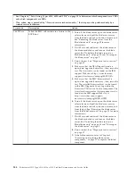
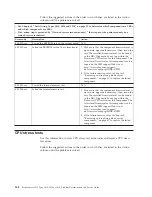
Page 148: ...DSA Diagnostic code is up to date upgrade if necessary then rerun the test The latest code can be found on the IBM support Web site at http www ibm com support docview wss uid psg1SERV DSA 5 Make sur...

Page 149: ...Rerun the test See Diagnostic tools overview on page 67 4 Make sure that the DSA Diagnostic code is up to date upgrade if necessary then rerun the test The latest code can be found on the IBM support...

Page 150: ...www ibm com support docview wss uid psg1SERV DSA 5 Make sure that the component firmware level is up to date upgrade if necessary then rerun the test The installed firmware level can be found in the D...

Page 151: ...agnostic tools overview on page 67 4 Make sure that the DSA Diagnostic code is up to date upgrade if necessary then rerun the test The latest code can be found on the IBM support Web site at http www...

Page 152: ...s up to date upgrade if necessary then rerun the test The latest code can be found on the IBM support Web site at http www ibm com support docview wss uid psg1SERV DSA 5 Make sure that the BMC firmwar...

Page 153: ...erun the test The latest code can be found on the IBM support Web site at http www ibm com support docview wss uid psg1SERV DSA 5 Make sure that the BMC firmware level is up to date upgrade if necessa...

Page 154: ...found on the IBM support Web site at http www ibm com support docview wss uid psg1SERV DSA 5 Make sure that the BMC firmware level is up to date upgrade if necessary then rerun the test The installed...

Page 155: ...test The latest code can be found on the IBM support Web site at http www ibm com support docview wss uid psg1SERV DSA 5 Make sure that the BMC firmware level is up to date upgrade if necessary then...

Page 156: ...found on the IBM support Web site at http www ibm com support docview wss uid psg1SERV DSA 5 Make sure that the BMC firmware level is up to date upgrade if necessary then rerun the test The installed...

Page 157: ...en rerun the test The latest code can be found on the IBM support Web site at http www ibm com support docview wss uid psg1SERV DSA 5 Make sure that the BMC firmware level is up to date upgrade if nec...

Page 158: ...y then rerun the test The latest code can be found on the IBM support Web site at http www ibm com support docview wss uid psg1SERV DSA 6 Make sure that the BMC firmware level is up to date upgrade if...

Page 159: ...BM support Web site at http www ibm com support docview wss uid psg1SERV DSA 5 Make sure that the BMC firmware level is up to date upgrade if necessary then rerun the test The installed firmware level...

Page 160: ...view wss uid psg1MIGR 4JTS2T 2 If the failure remains refer to Chapter 5 Removing and replacing blade server components on page 31 to replace the failed component 405 003 xxx Passed the Internal memor...

Page 161: ...on the IBM support Web site at http www ibm com support docview wss uid psg1SERV DSA 3 Make sure that the system firmware level is up to date upgrade if necessary then rerun the test The installed fir...

Page 162: ...te at http www ibm com support docview wss uid psg1SERV DSA 3 Make sure that the system firmware level is up to date upgrade if necessary then rerun the test The installed firmware level can be found...

Page 163: ...l can be found in the DSA Diagnostic Event Log within the Firmware VPD section for this component The latest level firmware for this component can be found on the IBM support Web site at http www ibm...

Page 164: ...3 Rerun the test See Diagnostic tools overview on page 67 4 If the component failure remains refer to Chapter 5 Removing and replacing blade server components on page 31 to replace the failed compone...

Page 165: ...the Firmware VPD section for this component The latest level firmware for this component can be found on the IBM support Web site at http www ibm com support docview wss uid psg1MIGR 4JTS2T 4 If the c...

Page 166: ...est level firmware for this component can be found on the IBM support Web site at http www ibm com support docview wss uid psg1MIGR 4JTS2T 4 If the component failure remains refer to Chapter 5 Removin...

Page 167: ...4JTS2T 4 If the component failure remains refer to Chapter 5 Removing and replacing blade server components on page 31 to replace the failed component 201 885 xxx Aborted the memory self test because...

Page 168: ...lade server components on page 31 to replace the failed component 201 894 xxx Aborted due to an unexpected error code 1 If the blade server has stopped responding turn off and restart the blade server...

Page 169: ...c code is at the latest level then rerun the test Diagnostic tools overview on page 67 The latest code can be found on the IBM support Web site at http www ibm com support docview wss uid psg1SERV DSA...

Page 170: ...media tray 3 Make sure that the cable for the optical drive is not damaged then replace the cable if damage is present See your BladeCenter documentation for information about replacing the optical d...

Page 171: ...tation for information about the optical drive media tray 5 Make sure that the cable for the optical drive is not damaged and replace the cable if damage is present See your BladeCenter documentation...

Page 172: ...drive media was not detected 1 Insert a new CD or DVD into the drive and wait for 15 seconds for the media to be recognized then rerun the test See Diagnostic tools overview on page 67 2 Make sure tha...

Page 173: ...BladeCenter documentation for information about the optical drive media tray 3 Make sure that the cable for the optical drive is not damaged and replace the cable if damage is present See your BladeC...

Page 174: ...l drive is not damaged then replace the cable if damage is present See your BladeCenter documentation for information about replacing the optical drive media tray 4 Make sure that the DSA Diagnostic c...

Page 175: ...tools overview on page 67 5 For additional troubleshooting information go to http www ibm com support docview wss uid psg1MIGR 41559 6 Rerun the test See Diagnostic tools overview on page 67 7 Replace...

Page 176: ...as terminated by the user N A Tape alert flags Use this information to diagnose and resolve tape alert flags for the blade server Tape alert flags are numbered 1 through 64 and indicate a specific med...

Page 177: ...ailure during an update The flash memory of the blade server consists of a primary page and a backup page If the BIOS code in the primary page is damaged the baseboard management controller will detec...

Page 178: ...ptions Attention Do not type Y when you are prompted to back up the ROM location doing so causes the damaged BIOS to be copied into the backup page 13 When you are prompted whether you want to move th...

Page 179: ...enter resource problems Use this information to diagnose and resolve shared BladeCenter resource issues Problems with BladeCenter shared resources might appear to be in the blade server The following...

Page 180: ...with the blade server See Keyboard or mouse problems on page 115 Media tray problems Use this information to diagnose and resolve media tray issues for the blade server To check for problems with the...

Page 181: ...damaged Try another CD or DVD if you have one v The software program is working properly b Continue with 6 6 For problems that affect one or more of the removable media drives a Reseat the following c...

Page 182: ...lace the management module see the documentation for your BladeCenter unit If these steps do not solve the problem it is likely a problem with the blade server See Network connection problems on page...

Page 183: ...olor monitor while it is turned on might cause screen discoloration Move the device and the monitor at least 305 mm 12 in apart Turn on the monitor To prevent diskette drive read write errors make sur...

Page 184: ...orking replace the bezel assembly then try to turn on the blade server from the management module see the documentation for the BladeCenter unit and management module for more information 3 Turn off t...

Page 185: ...ere made before the configuration failed Is this the original reported failure v Diagnostic program type and version level v Hardware configuration print screen of the system summary v BIOS code level...

Page 186: ...174 BladeCenter HS12 Type 8014 8028 or 1916 Problem Determination and Service Guide...

Page 187: ...ware and firmware if the problem has a documented solution within a software upgrade You can obtain the latest downloads for your system from http www ibm com systems support supportsite wss docdispla...

Page 188: ...ates To access these pages go to http www ibm com systems support You can find the most up to date product information for the IBM BladeCenter HS12 Type 8014 8028 and 1916 in http publib boulder ibm c...

Page 189: ...com planetwide In the U S and Canada call 1 800 IBM SERV 1 800 426 7378 In the U S and Canada hardware service and support is available 24 hours a day 7 days a week In the U K these services are avai...

Page 190: ...178 BladeCenter HS12 Type 8014 8028 or 1916 Problem Determination and Service Guide...

Page 191: ...ARTICULAR PURPOSE Some states do not allow disclaimer of express or implied warranties in certain transactions therefore this statement may not apply to you This information could include technical in...

Page 192: ...rtant notes Processor speed indicates the internal clock speed of the microprocessor other factors also affect application performance CD or DVD drive speed is the variable read rate Actual speeds var...

Page 193: ...the levels of particulates or gases in your environment have caused damage to the device IBM may condition provision of repair or replacement of devices or parts on implementation of appropriate remed...

Page 194: ...n radiate radio frequency energy and if not installed and used in accordance with the instruction manual may cause harmful interference to radio communications Operation of this equipment in a residen...

Page 195: ...rtment M456 IBM Allee 1 71137 Ehningen Germany Telephone 49 7032 15 2937 Email tjahn de ibm com Germany Class A statement Deutschsprachiger EU Hinweis Hinweis f r Ger te der Klasse A EU Richtlinie zur...

Page 196: ...schen EMVG das EG Konformit tszeichen CE zu f hren Verantwortlich f r die Einhaltung der EMV Vorschriften ist der Hersteller International Business Machines Corp New Orchard Road Armonk New York 10504...

Page 197: ...Communications Commission KCC statement Please note that this equipment has obtained EMC registration for commercial use In the event that it has been mistakenly sold or purchased please exchange it...

Page 198: ...186 BladeCenter HS12 Type 8014 8028 or 1916 Problem Determination and Service Guide...

Page 199: ...d installing 49 configuration Configuration Setup Utility 15 minimum 171 PXE Boot Agent Utility program 15 with ServerGuide 20 Configuration Setup Utility program 15 configuring SAS RAID array 22 conf...

Page 200: ...1501000 86 001501100 86 001501200 86 001501300 86 001501350 86 001501351 86 001501352 86 001501500 86 001501700 86 001501710 86 001501720 86 00150200 86 00150300 86 00150400 86 00150500 86 00150600 86...

Page 201: ...3 light path diagnostics 127 Light path diagnostics 67 light path diagnostics LEDs 130 light path diagnostics panel 13 light path LED locations 128 load default settings 16 logs BMC system event 76 Ma...

Page 202: ...ing electrical equipment vii setup with ServerGuide 20 software problems 126 software service and support telephone numbers 176 solving problems 113 specifications BladeCenter HS12 6 start options 16...

Page 203: ......

Page 204: ...Part Number 60Y1601 Printed in USA 1P P N 60Y1601...

Reviews: