


96
Chapter 7: Adding and removing adapter cards and drives
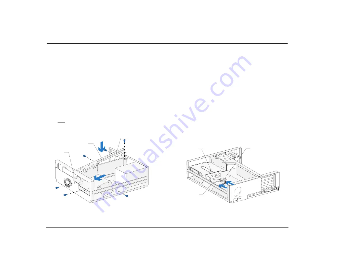
Installing a drive in bay 3 (continued)
3.
Right bracket replacement
Slide the right bracket into the bay. Make sure you
insert the catch into its slot on the front of the
system unit. Also make sure the riser card is
located to the left of the bracket.
Align the screw holes. Insert the two front screws
first, then insert the remaining screws. (The riser
card should be located to the left of the bracket so
that the screws go through the riser card first.)
Right Bracket
Catch
Riser Card
(Front View)
4.
Hard disk cable connections
Connect all drive cables. Reinstall any drives you
removed in bays 1 and 2. For instructions on
installing a drive in bay 1, see “Installing a drive in
bay 1” on page 91. For instructions on installing a
drive in bay 2, see “Installing a drive in bay 2” on
page 93.
(Back View)
Signal Cable
Power Cable
Drive
Summary of Contents for Aptiva
Page 1: ......
Page 4: ...iv Contents at a glance...
Page 12: ...xii Table of contents...
Page 16: ...2 Part 1 Learning about this book...
Page 22: ...8 Chapter 1 Using this book...
Page 24: ...10 Part 2 Controlling system settings...
Page 42: ...28 Chapter 3 Understanding the Rapid Resume features...
Page 62: ...48 Chapter 4 Viewing and changing Aptiva configuration...
Page 64: ...50 Part 3 Upgrading and replacing hardware...
Page 136: ...122 Part 4 Troubleshooting...
Page 164: ...150 Part 5 Technical reference...
Page 174: ...160 Appendix A Specification tables...
Page 194: ...180 Appendix C Modem information...
Page 196: ...182 Appendix D Monitor terminology...


