3. Operation
Fieldbus Communication
76
RCP6S
[Basic Operation Procedures]
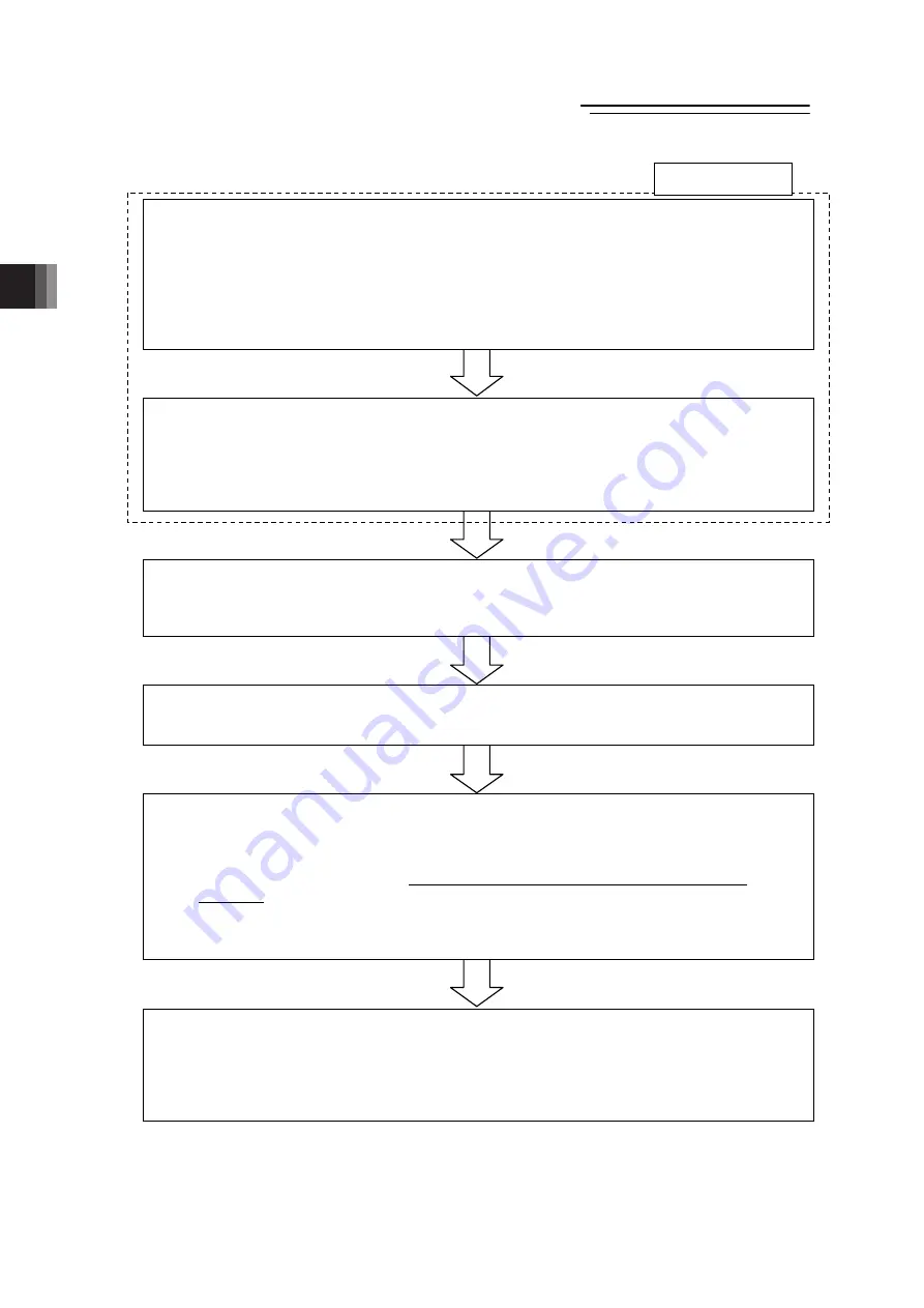
[1] Operation Mode Setting
[Refer to Sections 3.2.1 and 3.8]
Establish the settings for those such as the slave addresses in the Fieldbus using Gateway
Parameter Setting Tool. Establish the settings of the operation mode for all the axes.
1) Establish the setting following the procedure described in Section 3.2.1.
All the connected axes will be in the same operation mode.
2) Setting the gateway parameters to suit the system to be used.
Establish such conducting as the calendar function (clock setting) use or the speed unit
change in Direct Indication Mode.
[2] Parameter Settings [Refer to Sections 3.2.2]
Establish the parameter settings on all the connected axes by using a teaching tool such as
the PC software.
Set the zone (Parameters No.1 and 2) and soft limit (Parameter No.3 and 4) that suit to the
system.
[Refer to Chapter 8 Parameter]
[3] Setting of Position Data [Refer to Sections 3.3]
(Note) Setting of Direct Indication Mode is not necessary.
Set the data for those to be used such as target position, speed, etc. to the position
data.
[4] Fieldbus Settings [Refer to Sections 3.4.1 and 3.4.2]
Assign RCP6S gateway to PLC (master unit).
[Refer to the instruction manuals for the master unit and PLC]
[5] Link to Network
1) Put the operation mode setting switch on the front panel of RCP6S gateway unit to AUTO
side and reboot the power. (By putting to AUTO, Fieldbus line activates.)
2) Once the link to PLC (master unit) is established
(Note 1)
, turn ON MON Signal of the
gateway control signals
(Note 2)
. While MON Signal is ON, control from fieldbus is
available.
Note 1: By referring to 3.9 Fieldbus status LEDs display, confirm that the communication is
established in the normal condition.
Note 2: Refer to 3.4.2 Control Signals of Gateway.
[6] Operation Control in Each Operation Mode [Refer to Sections 3.4.3 to 3.4.8]
1) Send the information of the target position, speed, acceleration/deceleration, etc. from
PLC (master unit) to the RCP6S gateway.
2) The actuator follows the received information of the target position, speed,
acceleration/deceleration, etc. to perform a positioning at the specific coordinates.
3) Confirm the status of positioning complete.
Initial Setting
3.1.1
ME0349-4B
Summary of Contents for RCM-P6AC
Page 2: ......
Page 9: ...Fieldbus Communication RCP6S ME0349 4B ...
Page 32: ...Fieldbus Communication 20 RCP6S ME0349 4B ...
Page 86: ...2 Wiring Fieldbus Communication 74 RCP6S ME0349 4B ...
Page 178: ...3 Operation Fieldbus Communication 166 RCP6S ME0349 4B ...
Page 184: ...4 Vibration Suppress Control Function Fieldbus Communication 172 RCP6S ME0349 4B ...
Page 192: ...6 Power saving Function Fieldbus Communication 180 RCP6S ME0349 4B ...
Page 196: ...7 Absolute Reset Fieldbus Communication 184 RCP6S ME0349 4B ...
Page 284: ......
Page 285: ......


