


5. Practical Settings
126
[2] Position Data
There are two types in the coordinate conversion command, commands to make conversion in the
standard motion control position data (ECMD 280 to 282) and ones to make conversion in the
extension motion control position data (ECMD 290 to 292).
•
The axis numbers used in the coordinate conversion command are the numbers assigned in
order to be used for calculation. There is no relation to the axis numbers actually being connected.
For instance, even if the B-axis of the wrist unit is connected to Axis 1, it should be Axis 2 in the
coordinate conversion command.
In case that the axis number of the coordinate conversion command is different from the axis
number actually being connected, it is necessary to copy the value in the axis number after the
coordinate conversion to the connected axis number.
•
For the all axes extension motion (cartesian part (pulse motor) + wrist part (pulse motor)), use a
command to convert in the extension motion control position data (ECMD 290 to 292).
•
For the standard motion (cartesian part (AC servomotor) + extension motion (wrist part (pulse
motor)), use a command to convert in the standard motion control position data (ECMD 280 to
282), and then it is necessary to copy only the position of the extension motion (wrist part (pulse
motor)) to the extension motion position data.
Explained below is about each position and how to copy.
(Note) If it is not the axis structure to have the wrist unit rotated with a rotary axis, the posture
cannot be determined, thus the coordinates cannot be converted correctly. It is necessary
that the axis structure has the wrist axis + rotary axis.
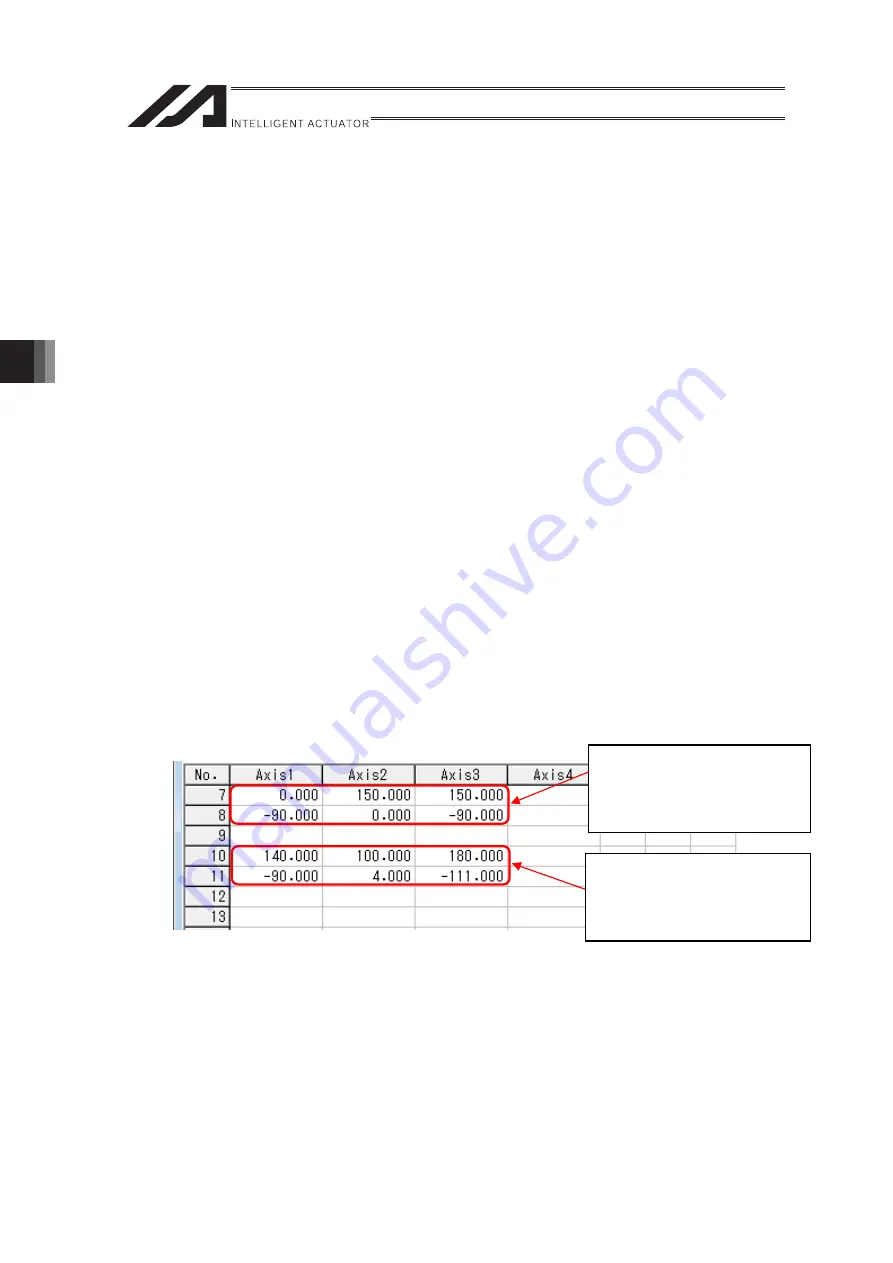
(1) Standard Motion Control Position Data
In a coordinate conversion command using the standard motion control position data, it is available
to handle positions for six axes by using two pieces of position data (first to third axis) in a row as
one set as shown in the figure below. Smaller position data number should be indicated for the
coordinate conversion command.
When moving to a position set in the standard motion control position data, use an operation
command such as MOVP.
(Note) For the data in “Work Coordinate Offset” and “Tool Coordinate Offset” explained in 5.3.5.
Coordinate Conversion Command, set in two pieces of position data as well as it is done in
the standard motion control position data.
Example for
Each Axis Coordinate System
Pn : (C1, C2, C3)
Pn+1 : (R, B, T)
Example for
Cartesian Coordinate System
Pn : (X, Y, Z)
Pn+1 : (Rx, Ry, Rz)
ME0364-2B
Summary of Contents for RA Series
Page 2: ......
Page 4: ...ME0364 2B ...
Page 22: ...1 Outline of Extension Motion Control Feature 14 ME0364 2B ...
Page 40: ...3 Basic Settings 32 ME0364 2B ...
Page 150: ...5 Practical Settings 142 ME0364 2B ...
Page 170: ...6 Parameter Detail 162 ME0364 2B ...
Page 174: ...7 Details of Features 166 ME0364 2B ...
Page 184: ......
Page 185: ......


