background image


8.6 How to replace components 

8-19 

8. Maintenan

ce and Inspection 


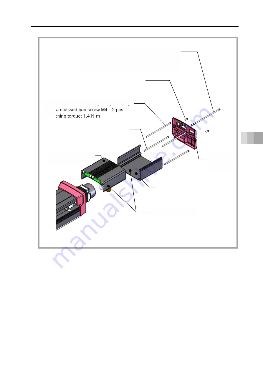
[For grounding connection] 

Cross-recessed pan screw M4    1 pc (for FG)

Tightening torque: 1.4 N·m 

Spring washer / Plane washer 1pc each 

[For end cover assembly fixation] 

Cross-recessed tapping screw M4    2 pcs 

Tightening torque: 0.8 N·m 

[For motor cover assembly (Top) fixation] 

Cross-recessed pan screw M4    2 pcs 

Tightening torque: 1.4 N·m 

End cover 

assembly 

Motor cover 

assembly (Top) 

Motor cover assembly 

Motor cover assembly (Bottom)

[For motor cover assembly (Bottom) 

fixation] 

Cross-recessed pan screw M4    2 pcs 

Tightening torque: 1.4 N·m 

Summary of Contents for ELECYLINDER EC-S13

Page 1: ...ictive Maintenance Parameters Troubleshooting Maintenance and Inspection External Dimensions Life Warranty Appendix ELECYLINDER ch 1 ch 2 ch 3 ch 4 ch 5 ch 6 ch 7 ch 8 ch 9 ch 10 ch 11 ch 12 Instruction Manual S15 S15X EC S13 S13X PSA 200 First Edition ME3801 1C ...

Page 2: ......

Page 3: ...e so that whoever is handling the product can refer to it quickly when necessary Important This instruction manual is an original document dedicated for this product This product cannot be used in ways not shown in this instruction manual IAI shall not be liable for any result whatsoever arising from the use of the product in any other way than what is noted in the manual The information contained...

Page 4: ...nual this document ME3801 PC Compatible Software for RC EC RCM 101 MW RCM 101 USB Instruction Manual ME0155 Touch Panel Teaching Pendant TB 02 02D Instruction Manual ME0355 Touch Panel Teaching Pendant TB 03 Instruction Manual Wireless communication ME0375 Touch Panel Teaching Pendant TB 03 Instruction Manual Wired communication For position controller ME0376 ...

Page 5: ... 1 27 Indicated grease applied type Model G5 1 27 Home reverse specification Model NM 1 27 PNP specification Model PN 1 27 Wireless communication specification Model WL 1 27 Wireless axis operation specification Model WL2 1 28 Two circuit power supply specification Model TMD2 1 28 1 4 Regenerative resistor unit option 1 29 Specifications of regenerative resistor unit 1 29 1 5 Accessories 1 30 Powe...

Page 6: ...ctuator main unit 3 16 Example for wiring actuator units and motor drive DC power supply PSA 200 3 19 3 4 Wiring connections for connectors 3 22 Power supply connector 3 22 Connectivity between actuator units and motor drive DC power supply 3 23 Regenerative resistor unit Option 3 25 24 V DC power supply wiring 3 27 PLC wiring 3 29 Connector wiring method 3 30 Brake release wiring 3 32 3 5 Wiring ...

Page 7: ...eter list 6 5 6 4 Parameter function descriptions 6 6 Parameter No 1 Operation range adjustment 6 6 Parameter No 2 Auto switch LS signal detection range adjustment 6 7 Parameter No 3 Change home return direction 6 8 Parameter No 4 Home position adjustment 6 9 Parameter No 5 Smooth accel decel setting 6 10 Parameter No 7 Wireless function setting 6 11 Chapter 7 Troubleshooting 7 1 Troubleshooting c...

Page 8: ...ent 8 23 Motor unit replacement 8 24 Replacement of intermediate support cushion 8 33 Fan replacement of motor drive DC power supply PSA 200 8 42 Chapter 9 External Dimensions 9 1 Slider type external dimensions 9 1 EC S13 9 1 EC S13X 9 2 EC S15 9 3 EC S15X 9 4 Motor drive DC power supply PSA 200 9 5 Chapter 10 Life 10 1 Concept of life for slider type 10 1 How to calculate operation life 10 1 Rel...

Page 9: ...Chapter 12 Appendix 12 1 Index 12 1 12 2 Revision history 12 5 ...

Page 10: ......

Page 11: ...Safety Guide Intro 1 Safety Guide The Safety Guide is intended to permit safe use of the product and thus to prevent risks and property damage Be sure to read it before handling the product ...

Page 12: ...ications Otherwise the product life may be drastically shortened and product damage or facilities stoppage may occur Do not use it in any of the following environments 1 Locations with flammable gases ignitable objects or explosives 2 Locations with potential exposure to radiation 3 Locations with ambient temperature or relative humidity exceeding the specifications range 4 Locations where radiant...

Page 13: ... Do not put anything heavy that could deform the package on it When using a crane with capacity of 1t or more have an operator qualified for crane operation and sling work When using a crane or equivalent equipment make sure not to suspend loads exceeding the equipment s rated load Use a hook that is suitable for the load Consider the safety factor of the hook in such factors as shear strength Als...

Page 14: ...o fire electric shock or abnormal operation due to leakage or conduction malfunction Perform the wiring for the product after turning OFF the power to the unit and avoid miswiring When wiring DC power 24V be careful with the positive negative polarity Incorrect connections may lead to fire product breakdown or abnormal operation Connect the cable connector securely so that there is no disconnectio...

Page 15: ...t insert fingers or objects into the openings in the product Otherwise this may lead to injury electric shock product damage or fire When releasing the brake on a vertically oriented actuator be careful that it does not fall under its own weight catching the operator s hand or damaging workpieces 5 Teaching When working with two or more persons make it clear who is to be in charge and communicate ...

Page 16: ...y lead to fire or damage to the product When a power failure occurs turn OFF the power switch Otherwise this may lead to injury or product damage due to unexpected product motion during recovery from the power failure 8 Maintenance and Inspection When working with two or more persons make it clear who is to be in charge and communicate well with each other to ensure safety Perform the work outside...

Page 17: ...protection fence the movable range should be indicated 9 Modification and Disassembly Do not modify disassemble assemble or use maintenance parts not specified on your own discretion 10 Disposal When the product exceeds its useful life or is no longer needed dispose of it properly as industrial waste When removing the actuator for disposal avoid dropping components when detaching screws Do not put...

Page 18: ...t is not handled correctly will result in death or serious injury Danger Warning This indicates a potentially hazardous situation which if the product is not handled correctly could result in death or serious injury Warning Caution This indicates a potentially hazardous situation which if the product is not handled correctly may result in minor injury or property damage Caution Notice This indicat...

Page 19: ...serve the usage conditions and environment of the product Operation outside the warranty could cause decreased performance or product breakdown Use within the allowable range for each item Item Cautions for use Problems or breakdowns which may occur if the allowable range is exceeded Speed and acceleration deceleration Use within the allowable range May lead to abnormal noise vibration breakdown o...

Page 20: ...oximately 5 cycles of return operation over a 50 mm distance or more to regenerate the oil film Continued use of the actuator in that state may lead to breakdown In extreme cases flaking may occur on the guide or ball screw 6 Do not attempt to have sliders collide with an obstacle at high speed This may damage other mechanical parts 7 The Allow mm or more indicated in the External Dimensions is in...

Page 21: ...y to EU Directives in some specific conditions as stated below you would be able to utilize this declaration EU Directives Applicable for EC Declaration of Conformity EMC Directive 2014 30 EU To be checked in CE marking described in product nameplate RoHS Directive 2011 65 EU Same as above RE Directive 2014 53 EU To be checked in EC Declaration of Conformity Low Voltage Directive 2014 35 EU Same a...

Page 22: ... within the following countries regions only Use in other countries regions requires certification to be obtained based on the laws and regulations of the relevant country region Wireless frequency 2 400 to 2 483 5 MHz Wireless output 5 dBm US This device complies with Part 15 of the FCC Rules Operation is subject to the following two conditions 1 This device may not cause harmful interference and...

Page 23: ...susceptible d en compromettre le fonctionnement IC RF Radiation Exposure Statement To comply with IC RF exposure requirements this device and its antenna must not be co located or operating in conjunction with any other antenna or transmitter Pour se conformer aux exigences de conformité RF canadienne l exposition cet appareil et son antenne ne doivent pas étre co localisés ou fonctionnant en conj...

Page 24: ...인명안전과 관련된 서비스는 할 수 없습니다 ประเทศไทย Thailand ผู ผลิต IAI CORPORATION ชื อโมเดล IABL3826 ประเทศผู ผลิต ญี ปุ น Made in Japan ผู นําเข า IAI Robot Thailand Co Ltd México Mexico Número de Certificación IFT RCPIATB19 1956 A1 Nombre de la Empresa Solicitante IAI Corporation Nombre del Modelo IABL3826 País de Fabricación Japón Hecho en Japón Nombre de la Empresa Importadora IAI America Inc ...

Page 25: ... with wireless connection operation testing movement to forward and backward ends jog operation inching operation is possible but the control device is not designed for purposes of automatic operation Construct a mechanical system based on the risks of the operating environment Carry out risk assessment based on the standard spec requirements of the machinery for installation Dangerous operation s...

Page 26: ...In this manual the ELECYLINDER s left right sides and motor opposite sides are shown as in the figure below Screw cover Slider Base Front bracket cover Motor cover Rear bracket cover End cover Opposite motor side Motor side Right side Left side ...

Page 27: ...rge status LED It is the LED to show that the internal circuit is being charged Power I O connector This connector connects power and I O wiring Motor power supply connector It is a connector establish connectivity to the PSA 200 power source This supplies power to the motor Warning Do not attempt to touch the product when the battery charge status LED is turned on in red You may get electrical sh...

Page 28: ...tor drive DC power supply PSA 200 Fan unit Status output connector Status indicator LED Power supply connector Grounding terminal Charge status LED Regenerative unit connector Motor power supply connector Fan unit connector ...

Page 29: ...he status of the control power supply the status of the motor power supply and the alarm status should be shown in LED display Power supply connector It is a connector for AC power supply connectivity It provides division input to the control power supply side and the motor power supply side Grounding terminal It is a screw for protection grounding Do not fail to have it conducted Charge status LE...

Page 30: ...ch the product when the battery charge status LED is turned on in red You may get electrical shock Make sure to turn the power off and to confirm that the battery charge status LED is turned off before touching the product for such purposes inspection ...

Page 31: ...atio 1 25 1 3 Options 1 27 RCON EC connection specification Model ACR 1 27 With brake Model B 1 27 Indicated grease applied type Model G5 1 27 Home reverse specification Model NM 1 27 PNP specification Model PN 1 27 Wireless communication specification Model WL 1 27 Wireless axis operation specification Model WL2 1 28 Two circuit power supply specification Model TMD2 1 28 1 4 Regenerative resistor...

Page 32: ...1 5 Accessories 1 30 Power I O cable 1 30 Power I O connector 1 31 Motor power supply cable 1 32 ...

Page 33: ...arts come to light contact your local IAI distributor Main unit of ELECYLINDER Body Accessories ELECYLINDER Quantity 1 Power I O cable Quantity 1 Power I O connector Quantity 1 Accessories Motor power supply cable Quantity 1 Protective cap Quantity 1 Connector guard Quantity 1 Hex socket head cap screw M3 5 Quantity 2 Accessories Documents DVD Quick Start Guide Quantity 1 Safety Guide Quantity 1 I...

Page 34: ...upply PSA 200 Power supply Quantity 1 To be prepared separately Note One unit to one axis to six axis of ELECYLINDER Accessories Power supply connector Quantity 1 Status output connector Quantity 1 Accessories Documents DVD Safety Guide Quantity 1 Instruction Manual Actuator DVD Quantity 1 ...

Page 35: ...1 1 Checking the product 1 3 1 Specifications How to read the model nameplate ELECYLINDER Model number Serial number ...

Page 36: ...1 1 Checking the product 1 4 1 Specifications How to read the model nameplate Motor drive DC power supply PSA 200 100 V Type 200 V Type Model number Serial number Model number Serial number ...

Page 37: ...15X 100 mm to 1100 mm S13 800 mm to 2000 mm S13X Blank Battery less absolute specification NPN specification no option B Brake ACR RCON EC connection specification G5 Indicated grease applied type NM Non motor end specification PN PNP specification WL Wireless communication specification Cable length 0 With power I O connector 1 to 10 With relay cable with cover 0 0 m 10 10 m 1 1 m 0 Equipped with...

Page 38: ... to 1100 per 50 st 1500 27 5 4 20 1000 40 5 9 10 5 500 18 S13X 132 96 7 132 mm 30 800 to 2000 per 50 st 27 1500 5 4 20 40 5 1000 9 10 500 18 5 250 30 6 81 81 90 S15 102 8 156 156 mm 40 100 to 1300 per 50 st 2000 36 9 20 1000 81 18 10 500 36 S15X 156 102 8 156 mm 40 1000 to 2500 per 50 st 36 1500 9 20 81 1000 18 10 500 36 108 108 113 9 170 9 113 9 170 9 341 8 250 30 6 90 683 6 341 8 683 6 169 6 339...

Page 39: ...mm 900 mm 950 mm 1000 mm 1050 mm 1100 mm 30 1500 1458 1297 1161 1045 946 860 785 720 663 20 1000 972 865 774 697 630 573 524 480 442 10 500 486 432 387 348 315 287 262 240 221 5 250 243 216 193 174 158 143 131 120 110 Unit mm s Caution The maximum speed may not be achieved when the stroke or movement distance is short or when acceleration deceleration is set low Setting at or below the minimum spe...

Page 40: ... 0 5 G in the horizontal direction and 0 3 G in the vertical direction For input 1 0 G is set as 100 0 3 G should be set as 30 and 0 5 G as 50 Lead 30 Maximum speed mm s Horizontal Vertical Acceleration G 0 3 0 5 0 7 1 0 0 3 0 5 0 7 1500 27 0 21 6 15 3 10 8 5 4 5 0 4 1 Unit kg Lead 20 Maximum speed mm s Horizontal Vertical Acceleration G 0 3 0 5 0 7 1 0 0 3 0 5 0 7 1000 40 5 31 5 20 7 13 5 9 0 7 7...

Page 41: ...hanical specifications 1 9 1 Specifications Caution Do not attempt to configure settings for acceleration deceleration above the allowable values This may lead to vibration breakdown or shortened product life ...

Page 42: ... 250 N m Brake type option Non excitation brake Brake hold torque option Lead 30 5 4 kgf Lead 20 9 0 kgf Lead 10 18 0 kgf Lead 5 30 6 kgf Ambient operatingtemperature humidity 0 to 40 C 85 RH or less Non condensing Motor type AC servo motor 200 W Number of encoder pulse 16384 pulse rev Overhang load length guideline 600 mm or less For reference rated life of 10 000 km The running life differs acco...

Page 43: ...ffset datum position Caution If the actuator is used with excessive allowable moment and overhang load it may not only lead to abnormal noise and vibration but also significantly reduce the life of the ELECYLINDER Allowable moment offset datum position 90 58 32 ...

Page 44: ... mm 1950 mm 2000 mm 30 1500 1450 1380 1314 1254 1197 1144 1095 1049 1005 964 20 1000 966 920 876 836 798 763 730 699 670 643 10 500 483 460 438 418 399 381 365 350 335 321 5 250 242 230 219 209 200 191 182 175 168 161 Unit mm s Caution The maximum speed may not be achieved when the stroke or movement distance is short or when acceleration deceleration is set low Setting at or below the minimum spe...

Page 45: ... 0 5 G in the horizontal direction and 0 3 G in the vertical direction For input 1 0 G is set as 100 0 3 G should be set as 30 and 0 5 G as 50 Lead 30 Maximum speed mm s Horizontal Vertical Acceleration G 0 3 0 5 0 7 1 0 0 3 0 5 0 7 1500 27 0 21 6 15 3 10 8 5 4 5 0 4 1 Unit kg Lead 20 Maximum speed mm s Horizontal Vertical Acceleration G 0 3 0 5 0 7 1 0 0 3 0 5 0 7 1000 40 5 31 5 20 7 13 5 9 0 7 7...

Page 46: ...hanical specifications 1 14 1 Specifications Caution Do not attempt to configure settings for acceleration deceleration above the allowable values This may lead to vibration breakdown or shortened product life ...

Page 47: ... 250 N m Brake type option Non excitation brake Brake hold torque option Lead 30 5 4 kgf Lead 20 9 0 kgf Lead 10 18 0 kgf Lead 5 30 6 kgf Ambient operatingtemperature humidity 0 to 40 C 85 RH or less Non condensing Motor type AC servo motor 200 W Number of encoder pulse 16384 pulse rev Overhang load length guideline 600 mm or less For reference rated life of 10 000 km The running life differs acco...

Page 48: ...ffset datum position Caution If the actuator is used with excessive allowable moment and overhang load it may not only lead to abnormal noise and vibration but also significantly reduce the life of the ELECYLINDER Allowable moment offset datum position 90 58 32 ...

Page 49: ...300 mm 1250 mm 1300 mm 40 2000 1922 1736 1575 1436 1315 1208 1114 1030 955 889 829 20 1000 961 868 788 718 657 604 557 515 478 444 414 10 500 481 434 394 359 329 302 278 258 239 222 207 Unit mm s Caution The maximum speed may not be achieved when the stroke or movement distance is short or when acceleration deceleration is set low Setting at or below the minimum speed may lead to abnormal noise or...

Page 50: ...is set as 100 0 3 G should be set as 30 and 0 5 G as 50 Lead 40 Maximum speed mm s Horizontal Vertical Acceleration G 0 3 0 5 0 7 1 0 0 3 0 5 0 7 2000 36 0 28 8 20 7 15 3 9 0 7 7 6 3 Unit kg Lead 20 Maximum speed mm s Horizontal Vertical Acceleration G 0 3 0 5 0 7 1 0 0 3 0 5 0 7 1000 81 0 63 0 42 3 27 0 18 0 15 3 12 6 Unit kg Lead 10 Maximum speed mm s Horizontal Vertical Acceleration G 0 3 0 5 0...

Page 51: ...irection 384 N m Brake type option Non excitation brake Brake hold torque option Lead 40 9 0 kgf Lead 20 18 0 kgf Lead 10 36 0 kgf Ambient operatingtemperature humidity 0 to 40 C 85 RH or less Non condensing Motor type AC servo motor 400 W Number of encoder pulse 16384 pulse rev Overhang load length guideline 750 mm or less For reference rated life of 10 000 km The running life differs according t...

Page 52: ...ffset datum position Caution If the actuator is used with excessive allowable moment and overhang load it may not only lead to abnormal noise and vibration but also significantly reduce the life of the ELECYLINDER Allowable moment offset datum position 95 63 32 ...

Page 53: ...m 2350 mm 2400 mm 2450 mm 2500 mm 40 1500 1486 1431 1378 1329 1282 1237 1195 1155 20 1000 991 948 909 871 836 803 772 743 715 689 664 641 619 598 578 10 500 495 474 454 436 418 402 386 371 358 345 332 320 309 299 289 Unit mm s Caution The maximum speed may not be achieved when the stroke or movement distance is short or when acceleration deceleration is set low Setting at or below the minimum spee...

Page 54: ...is set as 100 0 3 G should be set as 30 and 0 5 G as 50 Lead 40 Maximum speed mm s Horizontal Vertical Acceleration G 0 3 0 5 0 7 1 0 0 3 0 5 0 7 2000 36 0 28 8 20 7 15 3 9 0 7 7 6 3 Unit kg Lead 20 Maximum speed mm s Horizontal Vertical Acceleration G 0 3 0 5 0 7 1 0 0 3 0 5 0 7 1000 81 0 63 0 42 3 27 0 18 0 15 3 12 6 Unit kg Lead 10 Maximum speed mm s Horizontal Vertical Acceleration G 0 3 0 5 0...

Page 55: ...irection 384 N m Brake type option Non excitation brake Brake hold torque option Lead 40 9 0 kgf Lead 20 18 0 kgf Lead 10 36 0 kgf Ambient operatingtemperature humidity 0 to 40 C 85 RH or less Non condensing Motor type AC servo motor 400 W Number of encoder pulse 16384 pulse rev Overhang load length guideline 750 mm or less For reference rated life of 10 000 km The running life differs according t...

Page 56: ...ffset datum position Caution If the actuator is used with excessive allowable moment and overhang load it may not only lead to abnormal noise and vibration but also significantly reduce the life of the ELECYLINDER Allowable moment offset datum position 95 63 32 ...

Page 57: ...ical specifications 2 Figure out the acceleration deceleration time ratio tod using the calculation formulae below 指令加減速度が定格加減速度以上の場合 指令加減速度が定格加減速度以下の場合 負荷率 LF 指令加速度の可搬質量 Md kg 動作時の搬送質量 M kg 動作時の加減速度 α G M α Md α M Md 負荷率 LF 定格加速度の最大可搬質量 Mr kg 定格加減速度 αr G 動作時の搬送質量 M kg 動作時の加減速度 α G M α Mr αr Max payload at acceleration 0 3 G Mr kg Payload during operation M kg Acceleration during operation α G Loa...

Page 58: ...time ratio e g The reference for duty when the load factor LF is 80 and the acceleration deceleration time ratio tod is 80 should be approximately 75 0 20 40 60 80 100 0 20 40 60 80 100 加減速度時間比率tod デューティーの目安 LF 60 LF 50 未満 約75 LF LF LF LF 70 80 90 100 負荷率 Load factor Acceleration deceleration time ratio tod Reference for duty Approximately 75 ...

Page 59: ...hinery grade grease White Alcom Grease Home reverse specification Model NM The standard home position is on the motor side However the opposite side specification is selected if the home position direction is reversed in accordance with equipment layout or assembly direction PNP specification Model PN I O input output specifications are NPN specification as standard Specifying this option changes ...

Page 60: ...rol device is not designed for purposes of automatic operation Be sure to refer to the Precautions for Axis Operation with Wireless Communication Certification and self declaration regarding the wireless function are handled with the wireless circuit board model name below Model name IABL3826 Note Changes from WL to WL2 and from WL2 to WL cannot be performed by the customer Please contact us Two c...

Page 61: ...h install this regenerative resistor unit externally Model codes and specifications of enclosed items Item Enclosed Items Model Screw attachment small type RESU 1 Regenerative resistor unit connection cable Model code CB ST REU010 1 m enclosed DIN rail attachment small type RESUD 1 Specification RESU 1 RESUD 1 Body size mm W34 H154 D106 5 W34 H158 D115 Body mass Approx 0 4 kg Internal regenerative...

Page 62: ...site side of the connector has not been processed The cable length is available from 1 m to 10 m Specify the length in increments of 1 m The following shows a sample model number Cable length 1 m CB EC PWBIO010 RB Cable length 3 m CB EC PWBIO030 RB Cable length 10 m CB EC PWBIO100 RB ST0 ST1 RES ALM Note 1 TMD2 is 24V control Note Cable in light green and light gray not in use ...

Page 63: ... 5 Accessories 1 31 1 Specifications Power I O connector Supplied when cable length is specified as 0 in the model number Name Model number Quantity Power I O connector 1 1871940 6 Tyco Electronics 1 pc ...

Page 64: ...E 3 3 PE Green Yellow AWG18 The cable length is available from 1 m to 10 m Specify the length in increments of 1 m The following shows a sample model number Cable length 1 m CB EC PW010 RB Cable length 3 m CB EC PW030 RB Cable length 10 m CB EC PW100 RB Minimum bending radius r 40 mm or more for movable use Robot cable is standard for this model Actuator side 29 2 φ6 6 29 2 L 14 15 7 2 CN2 CN1 PSA...

Page 65: ...Storage preservation environment 2 3 2 3 Installation of Slider type 2 4 Installation surface 2 4 Mounting orientation Type S13 S13X S15 S15X 2 5 Fixing bolt 2 7 Body mounting 2 8 Mounting transported objects 2 9 2 4 How to Install motor drive DC power supply PSA 200 2 10 How to install Orientation of installation 2 10 ELECYLINDER Chapter ...

Page 66: ......

Page 67: ...the unit by its motor cover Do not damage or drop the package during transportation Do not apply excessive force to any part of the ELECYLINDER The teaching port and power I O connector are connected to the built in controller so be especially careful not to apply external force For the names of each part refer to Part Names on page Intro 16 to 20 Handling when assembled into machinery system Secu...

Page 68: ...the relative humidity exceeds 85 RH Where the unit receives direct sunlight Where the unit is exposed to corrosive or combustible gases Where the ambient air contains a large amount of dust salt or iron at levels exceeding those typical of an assembly plant Where the unit is subject to splashed water or oil including oil mist or cutting fluid or chemical solutions Where the body receives impact or...

Page 69: ...lly specified desiccant is not included in the package at shipping If the product is to be stored preserved in an environment where condensation is anticipated take condensation preventive measures For short term storage it can be stored at 60 C or below For storage of one month or more make sure that the temperature does not exceed 50 C The product should be placed horizontally for storage and pr...

Page 70: ...ting frame should have a structure rigid enough to prevent the generation of vibration Also consider the necessary space for maintenance work such as ELECYLINDER replacement and inspection The bottom surface and left side surface viewed from motor opposite side of the body base serve as the datum surfaces for slider running accuracy Use these surfaces as the datum surfaces for mounting when runnin...

Page 71: ...Installation of Slider type 2 5 2 Installation Mounting orientation Type S13 S13X S15 S15X Horizontal installation Vertical installation Horizontal lateral installation Horizontal ceiling mount installation ...

Page 72: ...rp and interfere with a workpiece Keep a workpiece attached to a position away from the slider When installing the unit vertically keep the motor on top to the greatest extent possible If the motor is installed on the bottom the grease may separate due to long term disuse causing the base oil to flow into the motor part and leading to controller or motor encoder breakdown Also there is a concern t...

Page 73: ... sure the internal thread and bolt effective engagement length is 1 5 times the nominal diameter or more Unless otherwise specified for tightening torque tighten screws with torque described in the table below For installation of the main unit apply the torque for When screw seat is aluminum Fixing bolt Tightening torque When screw seat is steel Tightening torque When screw seat is aluminum M8 30 ...

Page 74: ... pins Use the reamed hole and oblong hole if mounting reproducibility after detachment is required When fine adjustment of angles etc is required consider using only the reamed hole Type A mm B mm C mm D mm E mm EC S13 EC S13X 109 φ9 41 5 φ14 50 EC S15 EC S15X 133 φ9 41 5 φ14 50 Type Reamed hole Oblong hole EC S13 EC S13X φ8H7 depth 10 From base seat surface F 8 G 10 depth 10 mm or less EC S15 EC ...

Page 75: ... the screw in depth and reamed hole depth Refer to Chapter 9 External Dimensions for details Type A mm B mm Reamed hole EC S13 EC S13X 120 90 φ8H7 depth 10 EC S15 EC S15X 150 90 φ8H7 depth 10 Caution Be careful with regard to the length of the mounting bolt and positioning pin The use of screw in depth greater than that of the tapped or reamed mounting holes may damage the tapped hole or reduce th...

Page 76: ...as shown in the figure below for orientation Air flow for forced air cooling Orientation of installation inside control panel Follow the figure below for the minimum distance to a wall and the minimum distance to peripheral devices Design and build the control panel considering the ambient temperature for use of this power supply unit falling into the temperature range from 0 degC to 55 degC at th...

Page 77: ...ons of actuator main unit 3 9 Status output connector for motor drive DC power supply PSA 200 3 10 Number of connectable regenerative resistor units Option Reference 3 11 Brake release method for brake equipped type 3 12 Grounding terminal Actuator main unit 3 12 Grounding terminal motor drive DC power supply PSA 200 3 13 3 3 Connection arrangement diagram 3 14 Motor drive DC power supply PSA 200 ...

Page 78: ...power supply 3 23 Regenerative resistor unit Option 3 25 24 V DC power supply wiring 3 27 PLC wiring 3 29 Connector wiring method 3 30 Brake release wiring 3 32 3 5 Wiring connections for cables 3 32 Power I O cable 3 32 Power I O cable connection 3 33 24 V DC power supply wiring 3 34 PLC wiring 3 36 Brake release wiring 3 37 ...

Page 79: ...ter Power I O cable Model CB EC PWBIO RB Cable for connecting power and PLC I O signals 24 V DC power supply Model PSA 24 EC connection unit Model REC GW RCON EC 4 It is a unit to connect to field network Power supply communication cable Model CB EC REC RB Cable for connecting actuator and EC connection unit Touch Panel Teaching Pendant Model TB 03 Touch Panel Teaching Pendant Model TB 02 PC softw...

Page 80: ...se 200 V to 230 V AC 10 Motor Power frequency range 50 60 Hz 5 Max motor wattage connectable 100 V AC type 800 W 200 V AC type 1600 W Motor power capacity 200 W 402 VA 400 W 804 VA Peek max power capacity 200 W 1206 VA 400 W 2412 VA Control power current 320 mA Motor power voltage output 280 V DC typ Motor power voltage input 280 V DC typ Control power capacity 14 5 VA Brake release power supply 2...

Page 81: ...m reset Input voltage 24 V DC 10 Input current 5 mA time Leakage current MAX 1 mA per point Isolation type Non isolated Output Number of output points 3 points Forwarding complete backwarding complete alarm Output voltage 24 V DC 10 Output current 50 mA per point Leakage current 2 V or less Isolation type Non isolated Data setting and input methods PC software Touch panel teaching pendant Data ret...

Page 82: ...rol power cut off Off MP Motor power output in normal Green light ON Drive cut off Off ALM ALM0 to ALM2 Display of alarm occurrence status and its detail Charge status display LED 2 Charge status display LED Preventive predictive maintenance LED on the right flashes in green and red in turns when the movement counts or the travel distance has exceeded the setting value or in overload warning Valid...

Page 83: ...e 0 075 mm Frequency 57 to 150 Hz Acceleration 9 8 m2 XYZ each direction Sweep time 10 min Number of sweep times 10 times Insulation resistance 500 V DC 10 MΩ Electric shock protection mechanism Class Ⅰ basic insulation Pollution degree 2 Cooling method Natural air cooling Cooling method Forced air cooling by fan unit Degree of protection IP20 ...

Page 84: ...its in the table above However the maximum number of axes connectable is six The motor wattages of ELECYLINDER should be as shown below Model Motor wattage EC S13 EC S13X 200 W EC S15 EC S15X 400 W Note The maximum length of the motor power supply cable CB EC PW RB between the main unit of ELECYLINDER and the motor drive DC power supply PSA 200 should be 10 m Even though the maximum number of the ...

Page 85: ...mum control transient current amperage VA Heat generation W Motor power supply heating value W Control power supply heating value W Fixed resistor heat generation W Model Motor wattage Motor power supply Control power supply Fixed resistor Power capacity VA Peek max power capacity VA Heat generation W Power capacity VA Heat generation W Heat generation W EC S13 EC S13X 200 W 402 1206 1 7 14 5 8 7 ...

Page 86: ...rrent that enables to cutoff the current even when a short circuit current is flown for the rated cutoff current Rated interrupting current Short circuit current Primary power capacity Power voltage Consider margin for the rated current on the circuit breaker Rated current for circuit breaker Motor power capacity VA AC input voltage Safety margin 1 2 to 1 4 times Selection of leak current breaker ...

Page 87: ...voltage MIN 18 V DC OFF voltage MAX 6 V DC Residual voltage 2 V or less Leakage current MAX 1 mA per point Leakage current MAX 0 1 mA per point Isolation type Non isolated from external circuitry Non isolated from external circuitry I O logic NPN PNP Caution In the PIO circuit both input and output are non isolated Make sure to have a grounding for external devices connected to ELECYLINDER such as...

Page 88: ...nts Rated load voltage 24 V DC 10 Max load current 50 mA per circuit Leakage current Max 0 1 mA per point Residual voltage 2 V or less Isolation type Photocoupler isolation When current higher than the maximum load current flows the circuit should break and the output should become open 24 V External power Load Internal power 10 Ω Signal output NPN connection 24 V External power Load Internal powe...

Page 89: ...The values shown in the table above is a reference assuming that an actuator is ran back and forth under the condition of rated acceleration deceleration rated load 1000 mm stroke and duty ratio at 50 2 Regenerative energy is absorbed also inside the controller In case it exceeds the capacity the excess assumed regenerative electric discharge alarm should be generated In such a case add a regenera...

Page 90: ...ng pages 3 32 and 3 37 Grounding terminal Actuator main unit The ELECYLINDER has a built in controller circuit board Make sure to perform grounding as shown in the figure below in order to prevent electric shock and electrostatic charge to improve noise durability performance and to control unexpected radiation Controller Other equipment Controller Other equipment Other equipment Make sure to grou...

Page 91: ...ck and electrostatic charge to improve noise durability performance and to control unexpected radiation Class D for grounding class Grounding No 3 in old standard Grounding resistance at 100 Ω or less Make sure to ground individually for each power supply and do not share it with other devices or link with them PSA 200 PSA 200 Other equipment Other equipment Other equipment Other equipment ...

Page 92: ...protector if necessary considering the power supply condition It is recommended to attach it even though it is not mandatory Parts name Model code Supplier Position to attach Noise filter NF2010A UP Note SOSHIN ELECTRIC CO LTD Attach in range of 300 mm or less from controller NAC 10 472 COSEL Surge protector R A V 781BWZ 2A Okaya ELECTRIC CO LTD Attach at the input terminal of noise filter L1 L2 L...

Page 93: ...3 15 3 Wiring 2 Regenerative resistor unit RB IN RB IN RB OUT RB OUT CB ST REU010 RB Regenerative resistor unit connector Regenerative resistor unit REU1 RESU 1 RESUD 1 Regenerative resistor unit REU1 RESU 1 RESUD 1 CB ST REU010 PSA 200 ...

Page 94: ...units to PSA 200 motor power supply It is available to have six axes at the maximum for connection The number of axes connectable should depend on the motor wattage Refer to Max units connectable to motor drive DC power supply PSA 200 Motor power supply cable Model CB EC PW RB Max cable length 10 m ...

Page 95: ...ckward complete For NPN specification Power I O connector A1 B3 B5 B4 A3 A4 A5 0 V BKRLS ST0 ST1 RES ALM LS0 LS1 0 V 24 V DC Ground Alarm clear Forward complete Alarm B1 24 V 24 V power supply Backward Forward 2 Power I O connector Here the wiring connection method with a power I O connector is introduced Caution Note 1 This switch releases the brake forcibly for actuators equipped with a brake Th...

Page 96: ...DC Ground Alarm clear Forward complete Alarm B1 24 V 24 V power supply driving source Backward Forward B2 24 V power supply control 24 V A2 Brake release BKRLS Here the wiring connection method with a power I O connector is introduced Two circuit power supply specification TMD2 Option Caution It should fall into the stop condition by cutting off the 24 V drive source signals Refer to Example for w...

Page 97: ...r stop of an actuator Example for wiring of standard type Caution There may be a case that you face to a condition described below in case the AC power gets cut off during operation of an actuator While in Acceleration Motor power supply voltage drop Sudden stop due to deviation alarm While in Deceleration Operation continues as commanded until an alarm gets generated MCCB NF PSA 24 Control Power ...

Page 98: ...PSA 200 3 Two circuit power supply specification Option Connection of PSA 200 status output signal Shown in the figure below is an example of the wiring diagram when having the PSA 200 status output signal connected to the TMD2 type Basically it behaves the same as the one shown in the figure above however it can immediately stop the ELECYLINDER operation when PSA 200 cuts off the motor power supp...

Page 99: ...he connectivity of the power supply I O connector and the status output connector on ELECYLINDER TMD2 type as shown in the diagram below Motor drive DC power supply PSA 200 Status output connector B1 B2 B3 B4 B5 B6 A1 A2 A3 A4 A5 A6 3 4 5 6 1 2 ELECYLINDER TMD2 specification 24 V DC 0 V PWR PWR MP MP ALM ALM 0 V 24 V Control 24 V Drive OUT0 OUT1 OUT2 RSV BKRLS IN0 IN1 IN2 RSV Power I O connector ...

Page 100: ...low and put it in the inlet 3 Tighten the terminal screw with using such as a slotted screwdriver The inlet closes and affixes the wire 4 Connect all the wires in the same manner and insert the enclosed connector to the power supply connector Pin No Connector labeled name Contents Applicable cable diameter 1 L1 Motor AC power input KIV 2 0 mm2 AWG14 2 L2 3 L1C Control AC power input KIV 0 75 mm2 A...

Page 101: ...actuator units and motor drive DC power supply using the motor power supply cable CB EC PW RB As the motor drive DC power supply is capable for connection of six axes there are six connectors prepared Actuator main unit Motor drive DC power supply Power supply connector Power supply connector Motor power supply cable Model CB EC PW RB Max length 10 m ...

Page 102: ...hold the locking feature hold the other side at the same time and then pull it out Also by tightening the matching parts of the connector guards and the connectors with a tie band concern of contact error at the connectors caused by vibration on the cables can be reduced Connector guard Lock Lock Push in a thin tool to a gap between the connector guard and the locking feature to hold the locking f...

Page 103: ...age Specifications of external regenerative resistor connector Item Items and Model Connector name External regenerative resistor connector RB Model Controller side GIC2 5 3 GF 7 62 Cable side GIF2 5 3 STF 7 62 Pin assignment Pin No Signal Name Items Applicable cable diameter 1 RB Regeneration resistor Motor drive DC voltage Dedicated cable is enclosed to regenerative resistor unit 2 RB Regenerati...

Page 104: ...CB ST REU indicates the cable length Example 010 1 m Controller side Display of cable model code Regenerative resistor unit side Wiring Color Signal No KIV 1 0 mm2 AWG17 Light blue RB 1 Brown RB 2 Green Yellow PE 3 No Signal Color Wiring 1 RB Light blue KIV 1 0 mm2 AWG17 2 RB Brown 3 PE Green Yellow ...

Page 105: ...terminal of the 24 V DC power supply Connect the A1 connector terminal and the 0 V terminal of the 24 V DC power supply Pin No Connector nameplate name Compatible wire diameter Required specifications B1 24 V KIV 0 75 mm2 AWG18 Control power voltage 24 V DC 10 Control power capacity 0 32 A Brake power supply 0 875 A when in overexcitation Option When teaching pendant used 0 15 A Wiring length 10 m...

Page 106: ...utting off the 24 V drive source PIN number B1 it turns to the stop condition Refer to Example for wiring actuator units and motor drive DC power supply PSA 200 Pin No Connector nameplate name Compatible wire diameter Required specifications A2 24 V Control KIV 0 75 mm2 AWG18 Control power voltage 24 V DC 10 Control power capacity 0 32 A Brake power supply 0 875 A when in overexcitation Option Whe...

Page 107: ...nput terminal Connect the A4 connector terminal and the Forward complete input terminal Connect the A5 connector terminal and the Alarm input terminal Pin No Connector nameplate name Signal abbreviation Compatible wire diameter Function overview B3 Backward ST0 KIV 0 20 mm2 AWG24 Backward command B4 Forward ST1 Forward command B5 Alarm clear RES Alarm clear A3 Backward complete LS0 Backward comple...

Page 108: ...ernal structure looks like this Insert a precision screwdriver fully into the tool insertion slot Press the spring within the connector down then insert the core wire slightly twisted Pulling out the precision screwdriver causes the spring within the connector to rebound clamping the core wire inserted in place A1 B1 A2 B2 A3 B3 A4 B4 A5 B5 A6 B6 Tool insertion slot Wiring inlet Wiring inlet Refer...

Page 109: ...ntion force causing the wire to fall out of the connector and possibly causing insufficient current or short circuit Do not insert the precision screwdriver violently into the connector or twist it hard This may damage the connector housing and internal spring If an electric wire thinner than the applicable diameter or wiring longer than 10 m is used insufficient current may trigger an alarm and t...

Page 110: ...en in overexcitation 0 085 A when steady is required Pin No Connector nameplate name Signal abbreviation Compatible wire diameter Required specifications B2 Brake release BKRLS KIV 0 20 mm2 AWG24 24 V DC 10 0 875 A when in overexcitation 0 085 A when steady 3 5 Wiring connections for cables Here the wiring connection method with a power I O cable is introduced Power I O cable Note1 TMD2 is 24V con...

Page 111: ...le length 10 m CB EC PWBIO100 RB Power I O cable connection Connect the power I O cable Insert the connector until it clicks into place Caution The connector must be inserted in a given direction A section of the connector protrudes Orient this section downwards and insert until it clicks into place Take appropriate care to prevent unused wiring in the loose wire end on the cable from shorting out...

Page 112: ...4 V terminal of the 24 V DC power supply Connect the 0 V wire insulation color black to the 0 V terminal of the 24 V DC power supply Wiring color Signal abbreviation Function overview Required specifications Red 24 V Power supply input Control power voltage 24 V DC 10 Control power capacity 0 32 A Brake power supply 0 875 A when in overexcitation Option When teaching pendant used 0 15 A Black 0 V ...

Page 113: ...black to the 0 V terminal of the 24 V DC power supply Wiring color Signal abbreviation Function overview Required specifications Light blue 24 V Control Control power supply input Control power voltage 24 V DC 10 Control power capacity 0 32 A Brake power supply 0 875 A when in overexcitation Option When teaching pendant used 0 15 A Black 0 V Ground By cutting off the 24V drive source insulation co...

Page 114: ...e yellow cable wire and the Forward output terminal Connect the green cable wire and the Alarm clear output terminal Connect the blue cable wire and the Backward complete input terminal Connect the purple cable wire and the Forward complete input terminal Connect the gray cable wire and the Alarm input terminal 3 8 PLC connection 3 4 5 6 7 8 PLC Process the terminals in accordance with PLC specifi...

Page 115: ...g a forcible brake release switch connect the brown cable wire Power capacity of 24 V DC 10 0 875 A when in overexcitation 0 085 A when steady is required Wiring color Signal abbreviation Function overview Required specifications Brown BKRLS Brake release 24 V DC 10 0 875 A when in overexcitation 0 085 A when steady ...

Page 116: ...3 38 3 Wiring ...

Page 117: ...ting adjustment 4 5 Stop position setting adjustment forward end backward end 4 6 Operating conditions AVD setting adjustment 4 7 4 4 I O signals 4 10 I O signal list 4 10 ST0 ST1 signals Movement command input backward forward 4 11 RES signal Alarm clear input 4 12 BKRLS input Brake release input 4 12 LS0 LS1 signals Position detection output backward end forward end 4 13 ALM signal Alarm output ...

Page 118: ...4 5 Operating method from master device 4 15 Positioning operation ST0 LS0 ST1 LS1 signals 4 15 ...

Page 119: ...n An input signal from a master device to the ELECYLINDER triggers operation of the ELECYLINDER The ELECYLINDER status can also be determined when the master device receives signal output from the ELECYLINDER Control is just as simple as when using a solenoid valve SOL valve and air cylinder drive This manual introduces an example using a PLC connected as the master device The ELECYLINDER continue...

Page 120: ... supply after turning it OFF ELECYLINDER Unit 1sec or more after turning 24 V DC power supply OFF Motor drive DC power supply PSA 200 2sec or more after turning 24 V DC power supply OFF Time required for ELECYLINDER startup Power supply to initialization Approx 3sec Order to turn power off Shown below is the recommended order to turn the power off There should be no problem even if the order is sw...

Page 121: ...l teaching pendant operation Touch panel teaching pendant manual method ME0375 ME0376 Caution Maximum stroke operation is configured at shipping Before operating the ELECYLINDER make sure to check there is nothing that will interfere with moving parts within the operation range Teaching pendant connection Connect the teaching pendant TB 02 while the power is OFF Insert the round connector of TB 02...

Page 122: ...r if the operating mode is not Monitor mode the Message screen will be displayed Switch to Monitor mode by following the displayed instructions If the position edit password is set to a value other than 0000 enter the password and press the ENT key on the touch panel The screen will switch to the Simple Data Setting window The position edit password is set to 0000 at shipping Refer to the teaching...

Page 123: ...ons AVD setting adjustment The stop position and operating conditions are set for the ELECYLINDER at shipping The Simple Data Setting screen can be used to adjust the stop position and operating conditions Caution Be sure to touch the Transfer key after configuring or adjusting data The data will return to the previous state if the screen is changed without pressing Transfer Moreover the Manual op...

Page 124: ...s of 0 01 mm Touch the position you want to configure adjust Ten Key window will open After setting the numerical value touch the ENT key Then touch the Transfer key A value will be written to the controller and the B End button and F End button will turn green Press the F End or B End buttons to operate Check the results of the new setting adjustment Note that pressing the button while operating ...

Page 125: ...button to switch the units to G allowing entries to be made in increments of 0 01 G The acceleration deceleration unit of G is described below 1G 9 800 mm s2 Acceleration possible up to 9 800 mm s per second For 0 3 G the acceleration per second is 9 800 mm s2 0 3 2 940 mm s2 The procedure on the following page can be used to configure adjust the operating conditions AVD Note that the ELECYLINDER ...

Page 126: ...lue will be displayed below the ten key pad To configure a new setting touch the Change key The Transport load setting window will open Select Installation orientation and enter the Transport load then touch the Set button The Optimal speed and Optimal acceleration deceleration for the shortest cycle time for the configured conditions will be displayed Action 2 1 Action 3 Action ...

Page 127: ...d the B End button and F End button will turn green The Transfer history will also be updated Present set value and Previous set value cycle time calculation results are updated Press the F End or B End buttons to operate Check the results of the new setting adjustment Caution If abnormal noise vibration or impacts occur when the ELECYLINDER is operated lower the acceleration and deceleration rate...

Page 128: ... will cause a gradual stop Forward ST1 Turning ON sends it forward Turning OFF midway through operation will cause a gradual stop Alarm clear RES Turning ON resets the alarm Brake release BKRLS Inputting 24 V DC releases the brake Output Backward complete LS0 ON when entering the backward end detection range Forward complete LS1 ON when entering the forward end detection range Alarm b contact ALM ...

Page 129: ...adual stop For details refer to 4 5 Operating method from master device Caution If stopped when the LS signals are not ON the ELECYLINDER may be stopped on the way to the backward or forward end We recommend first inputting the ST0 signal and then performing the following actions after returning to the backward end For the battery less absolute type the condition of the home return completed shoul...

Page 130: ...pacity requires 24 V DC 10 and 0 875 A when in overexcitation 0 085 A when steady The ELECYLINDER brake is a non excitation actuating solenoid brake In normal operation the brake is automatically released but when the servo is OFF or power is OFF the brake engages The brake must be released in order to move the movable part slider by hand Warning Before releasing the brake make sure to check there...

Page 131: ...forward ends They turn ON when within the detection range regardless of whether the servo is ON or OFF The backward end and forward end set values relationship to LS0 and LS1 signals ON is as follows In this example the LS signal detection range is 0 10 mm To adjust the LS signal detection range open the Edit parameters window Parameter No 2 Auto switch LS signal detection range adjustment can be ...

Page 132: ...ty countermeasures with the equipment as a whole For details refer to 7 4 Troubleshooting by alarm groups Signal input time constant In order to prevent mis operation due to chattering or noise ST0 ST1 and RES signals are set with a 6ms input time constant For signals less than 6ms the device will not consistently recognize the signal so input signals continuously for 6ms or longer 6 ms Input sign...

Page 133: ...m master device Positioning operation ST0 LS0 ST1 LS1 signals Turn ST0 Signal ON and the actuator drives to the backward end Turn ST1 Signal ON and the actuator drives to the forward end Backward signal ST0 Backward end signal LS0 ELECYLINDER movement Backward Backward end Backward ...

Page 134: ...the forward end 5 Input ST0 Moves to the backward end 6 Output LS0 Moved to the backward end 7 After this 3 to 6 repeat Δt1 The time taken for the ELECYLINDER actually to reach the forward or backward end after the LS signal turns ON Consider Δt1 when giving instructions for the next operation from the PLC to the ELECYLINDER Δt1 becomes longer for larger detection ranges Δt1 also changes with the ...

Page 135: ...ve reached the forward backward end Caution Turning the ST signal ON again after the gradual stop causes the ELECYLINDER to begin operation again Within the detection range the LS signal turns ON even if the ELECYLINDER is mid operation Make sure that ST0 and ST1 do not turn ON simultaneously This may result in unpredictable operation ST signal LS signal ELECYLINDER movement Original deceleration ...

Page 136: ...4 18 4 Operation ...

Page 137: ... 2 Maintenance information 5 2 Total travel count 5 2 Total travel distance 5 2 Overload warning level 5 3 Capacitor assumed life exceeded warning 5 4 5 3 Setting maintenance information 5 5 Switching to maintenance information window 5 5 Basic operation 5 6 ELECYLINDER Chapter ...

Page 138: ......

Page 139: ...t prompts the user to perform maintenance if the travel count or the travel distance exceeds the set values Preventative maintenance Predictive maintenance Maintenance that is performed when based on regular equipment monitoring an abnormality is predicted to occur Predicts unexpected breakdowns Prevents sudden line stoppages Regular maintenance that is performed based on a reference period regard...

Page 140: ...otal travel count exceeds the set value the user will be notified with Maintenance warning 1 When Maintenance warning 1 is output maintenance is recommended such as greasing Set the target value to a value larger than the present one and update Setting it to 0 times will disable this function Total travel distance Name Symbol Unit Input range Default setting at shipping Total travel distance ODOT ...

Page 141: ... rise value falls below the ratio set as overload warning level Maintenance warning 3 will be automatically cleared When Maintenance warning 3 is output investigate the cause of the increase in load Maintenance such as greasing or reviewing the operating conditions is recommended Setting it to 100 will disable this function Temperature change under abnormal conditions Temperature change under norm...

Page 142: ...is recommended to have the controller PC board replaced as early as possible Capacitor assumed life exceeded warning on motor drive DC power supply PSA 200 ALM1 in the status LED starting to blink shows the capacity has reached its end of life Refer to 7 1 Troubleshooting Confirmations 4 Check in status LED on motor drive DC power supply for ALM1 in the status LED The warning being generated is no...

Page 143: ...ME0155 Teaching pendant operating method Teaching pendant manual ME0355 Touch panel teaching pendant operation Touch panel teaching pendant manual method ME0375 ME0376 Switching to maintenance information window Touch Information on the Menu 1 screen The screen will switch to the Information window If the TP operation mode is not Monitor mode a confirmation window will appear for switching to Moni...

Page 144: ...e ENT key The target value will change If you touch ESC the target value will not be changed and the original window will return Touch the Information edit button A confirmation message for rebooting the controller will be displayed The setting change will take effect after rebooting If the actuator has been replaced touch the Actuator replacement button Total travel count and Total travel distanc...

Page 145: ... 4 Parameter function descriptions 6 6 Parameter No 1 Operation range adjustment 6 6 Parameter No 2 Auto switch LS signal detection range adjustment 6 7 Parameter No 3 Change home return direction 6 8 Parameter No 4 Home position adjustment 6 9 Parameter No 5 Smooth accel decel setting 6 10 Parameter No 7 Wireless function setting 6 11 ELECYLINDER Chapter ...

Page 146: ......

Page 147: ...ct settings may lead to mis operation When making a change back up the data before the change so the settings can be recovered Back up the data after making changes as well This will be required for investigating causes of failure or when the ELECYLINDER is replaced Caution Understand the control methods in advance if making a change or performing a setting in accordance with the system and applic...

Page 148: ...Menu 1 screen The screen will switch to the Edit parameters window If the TP operation mode is not Monitor mode a confirmation window will appear for switching to Monitor mode Also if the parameter edit password is set to a value other than 0000 the password input screen will be displayed If the parameter edit password is set to a value other than 0000 enter the password and press the ENT key on t...

Page 149: ...d touch the ENT key The parameter will be changed However if you touch ESC the parameter will not be changed and the edit window will return If setting parameters with radio buttons touch the radio buttons The parameter will be changed When all parameter changes are complete touch the Home button If parameters have been changed the Restart the controller screen will be displayed 1 Action 2 Action ...

Page 150: ...ation button displays a description of each parameter at the bottom of the screen Caution Simply changing the parameters alone is not sufficient to enable the changes After making changes the power must be turned off and on or a software reset performed After the ELECYLINDER restarts the parameter changes will be enabled Do not attempt to turn OFF the power while writing the parameters This may da...

Page 151: ...decel setting MOD0 Disabled enabled Disabled 6 10 7 A Wireless function setting RWOF Disabled enabled Disabled 6 11 The categories in the table below indicate whether parameters should be set or not There are 3 categories as follows Not displayed on PC compatible software teaching pendant screen A Check or change the settings based on the usage method B Use as set at shipping as a rule C Set at sh...

Page 152: ...m setting unit is 0 01 mm Set to your desired stroke length The controller automatically adds 0 30 mm and controls monitors the operation range Set the operating stroke between 0 and 80 mm by changing Parameter No 1 to 80 00 mm Caution Set within the ELECYLINDER movable range Setting to a value that exceeds the maximum stroke will result in collision with the forward side mechanical stopper This m...

Page 153: ...ete forward complete ON trigger range relative to the backward end forward end When the ELECYLINDER enters the detection range the backward complete or forward complete signal turns ON The minimum setting unit is 0 01 mm The LS signal detection range for the conditions below is shown in the figure Backward end 0 00 mm Forward end 100 00 mm Parameter No 2 0 10 mm Backward end 0 00 mm Forward end 10...

Page 154: ...rameter No 3 is Forward If Parameter No 3 is Reverse Caution Changing the home return direction reverses the operation direction After changing this parameter always perform home return reset absolute reset Even if the operation direction is reversed check that the moving parts do not interfere with any other objects If the moving parts collide they may damage the ELECYLINDER workpiece or peripher...

Page 155: ...ome return direction after purchase 3 To eliminate a slight deviation from the previous home position generated after replacing the ELECYLINDER If Parameter No 4 is 0 30 mm the relationship between mechanical stopper and home position is as follows Caution If adjusting Parameter No 4 simultaneously adjust Parameter No 1 Operation range adjustment with parameter No 1 uses the home position as the d...

Page 156: ...softens the shocks of acceleration deceleration without delaying the operation time If Disabled the above functionality is not enabled Setting Acceleration deceleration pattern Operation waveform image Disabled Trapezoid Enabled S motion Caution For operation in which the acceleration time or deceleration time exceeds 2 seconds do not Enable smooth accel decel settings Normal operation will not be...

Page 157: ...ELECYLINDER wireless function When Enabled is selected wireless communication between the ELECYLINDER and the Touch Panel Teaching Pendant is possible When Disabled is selected wireless communication between the ELECYLINDER and the Touch Panel Teaching Pendant is not possible There is no transmission or reception of wireless communication radio waves Caution This parameter is not displayed on ELEC...

Page 158: ...6 12 6 Parameters ...

Page 159: ...rm group B Motor abnormality alarm 7 15 Alarm group C Controller abnormality alarm 7 16 Alarm group D Controller encoder abnormality alarm 7 17 Alarm group E Supply voltage power capacity abnormality alarm 7 18 Alarm in motor drive DC power supply PSA 200 7 19 Warning Maintenance warning 1 7 20 Warning Maintenance warning 2 7 20 Warning Maintenance warning 3 7 21 Warning Maintenance warning 4 7 22...

Page 160: ......

Page 161: ...side as seen from the motor side Operation status ALM signal output status SV green ALM red Control power OFF OFF Servo OFF ON Alarm generated OFF Stop switch ON When using teaching pendant ON Control Power ON Servo ON ON Blinking in green 500 ms 1 Hz frequency Maintenance warning generated When the travel count or the travel distance has exceeded the set value or when overload warning is generate...

Page 162: ... status LED on ELECYLINDER unit Light ON Light OFF Blinking Motor Power Supply Status LED In the middle in the view from motor side Motor power supply status Green Red Motor power turned ON Motor power turned OFF Initializing when power comes ON In the middle in the view from motor side Green Red ...

Page 163: ...D Left side as seen from the motor side Wireless status Green Red Wireless not connected transmitting monitor data Connecting from wired teaching pendant ON 200 ms OFF 200 ms alternate blinking Wireless hardware error ON 150 ms OFF 150 ms alternate blinking Connecting through wireless Initializing when power comes ON Left side as seen from the motor side Green Red ...

Page 164: ... Cutoff Close Fan revolution drop warning Note 1 No Cutoff Close Motor power supply voltage drop No Cutoff Open Fan Error Detection Cutoff Open Excess regenerative electric discharge Cutoff Open Motor power supply excess voltage Cutoff Open PC board temperature error Cutoff Open Power device overheated Cutoff Open Critical malfunction Cutoff Open Initializing when power comes ON Both PWR and MP ar...

Page 165: ...he main power supply of the equipment to avoid electric shock and remove the cables around the measurement point to avoid conductivity through the surrounding circuit before checking the conductivity 11 Check the I O signals Use the master device and ELECYLINDER teaching tool to check for inconsistency or abnormality in the input output signal status of the two units 12 Check the noise elimination...

Page 166: ...th the diagnosis as follows When no alarm is generated Abnormal conditions can be roughly divided into the following two types For details and countermeasures see 7 3 Troubleshooting with no alarm generated Operation failure Abnormal or unstable operation If the issue is not resolved after checking and taking countermeasures contact IAI ...

Page 167: ...asure There was an error occurred in the controller PC board Replace the controller cover assembly D Controller encoder abnormality alarm Content Countermeasure There was an error occurred between the controller PC board and encoder Turn the power off and then on again In case there is no recovery confirmed replace the controller cover assembly or motor E Power supply voltage Power supply capacity...

Page 168: ...r to 3 4 3 5 Wiring connections 2 The unit is switched to servo OFF with the teaching tool Turn ON the servo with PC software or teaching pendant 3 Controller breakdown Replace the controller cover assembly For details refer to Controller replacement page 8 17 to 21 and 22 If the unit still does not recover contact IAI Condition 2 SV ALM LEDs light up red No Possible cause Confirmation countermeas...

Page 169: ...hinner than the applicable value Make sure the wiring processing is correct For details refer to 3 4 3 5 Wiring connections 2 Disconnection of power I O cable disconnection or contact failure of power I O connector Check whether the cable is disconnected partially disconnected Make sure that the connector and cable are not pulled out For details refer to 3 4 3 5 Wiring connections 3 Movement comma...

Page 170: ...tually having done so No Possible cause Confirmation countermeasure 1 A load exceeding the maximum payload is applied Reduce the load 2 A moving part is hitting interference while moving Remove the interfering object 3 The body or guide is twisted due to the fixing method of the ELECYLINDER Loosen the fixing bolt and check whether the moving part moves smoothly If it does check whether the mountin...

Page 171: ...lished Check the input output status of the LS signal I O signal with the monitoring function of the teaching tool Both the master device and the ELECYLINDER Make sure the LS signal I O signal voltage is normal Check whether the length of the I O signal cable is within 10 m and whether the wire diameter is thinner than the applicable value Make sure the wiring processing is correct For details ref...

Page 172: ...ation Lower the acceleration deceleration setting Enable Parameter No 5 Smooth accel decel setting and check its effect For details refer to 6 4 Parameter function descriptions 2 Load inertia is excessive Lower the deceleration and suppress overshoot Situation 4 The unit vibrates slightly while stopped No Possible cause Confirmation countermeasure 1 A load susceptible to vibration is mounted The E...

Page 173: ...n again Warning Green blinking ON Continued operation Maintenance Warnings 1 2 Total travel count Total travel distance are cleared by updating the set values in the maintenance information window Maintenance Warning 3 4 Overload warning Capacitor assumed Life exceeded warning are cleared by resetting the alarm Maintenance Warning 4 should occur again after power reboot Caution Clear alarms only a...

Page 174: ...ed when mounting the ELECYLINDER increasing the sliding resistance of the guide The ELECYLINDER mounting surface should be a machined surface or a plane with similar accuracy with flatness within 0 05mm m Refer to the recommended tightening torque of the bolts for base fixing in 2 3 Installation method 5 The power voltage on 100 V AC or 200 V AC has dropped Check on the power voltage of 100 V AC o...

Page 175: ...untermeasure examples Remove the heat source turn OFF the heat source install a fan install a temperature shield improve thermal conductivity of the base install a heat dissipation fin etc 2 The ELECYLINDER may be being used under conditions exceeding the specifications described in the catalog Check the specification values such as payload acceleration deceleration and speed and adjust them appro...

Page 176: ...DER then check to see whether this alarm persists If it does not there is a possibility that the ELECYLINDER is affected by the noise from the peripheral device Reconsider the noise countermeasures grounding power line wiring electrostatic shielding etc for the peripheral device 2 If this alarm recurs after performing the inspection above and improving the power supply environment it is highly lik...

Page 177: ...se from a peripheral device and disabled to work correctly Shut down the power supply of the peripheral device and operate only with the ELECYLINDER then check to see whether this alarm persists If it does not there is a possibility that the ELECYLINDER is affected by the noise from the peripheral device Reconsider the noise countermeasures grounding protection power line wiring electrostatic shie...

Page 178: ...easure 1 Use a tester to check if the power the power voltage on 24 V DC is in the range between 21 6 and 26 4 V If it is out of range the 24 V DC power supply voltage has insufficient capacity Refer to our catalog for the required capacity and improve the power supply environment Countermeasure 2 Check whether the length of the power I O cable is within 10m and whether the wire diameter is smalle...

Page 179: ...rge in the internal regenerative resistance has risen above the threshold 1 Add a regenerative resistor unit 4 Motor power supply excess voltage The output voltage has risen a above the threshold 1 Check on the motor drive DC power supply PSA 200 Check such things as power voltage 2 Add a regenerative resistor unit 5 PC board temperature error The thermo sensor on the PC board had detected an over...

Page 180: ...o a value larger than the current value For setting refer to 5 2 Maintenance information and 5 3 Setting maintenance information Warning Maintenance warning 2 This is an alert that the target value of the total travel distance set by the customer has been reached No Content Countermeasure 1 For safe use and long service life of the ELECYLINDER periodic lubrication is recommended To disable this wa...

Page 181: ...inside the ELECYLINDER intrusion of foreign matter brake failure motor failure contact with peripheral equipment etc Countermeasure 1 Visually check for the depletion of grease on the ball screw guide inside the ELECYLINDER intrusion of foreign matter etc If this is the case clean the inside of the ELECYLINDER and replenish the grease Refer to 8 4 Cleaning and 8 5 Greasing method Countermeasure 2 ...

Page 182: ...ntroller PC board is close to the end No Content Causes and countermeasures 1 The life of the capacitor mounted on the controller PC board has reached the end The warning being generated is not stating there is no capacity in the capacitor dry up however it is recommended to have the controller PC board replaced as early as possible ...

Page 183: ... power supply unit 2 Electrolytic capacitor life warning The electrolytic capacitor has reached the end of its life The warning being generated is not stating there is no capacity in the capacitor dry up however it is recommended to have the motor drive DC power supply replaced as early as possible 3 Fan revolution drop warning The fan revolution count has dropped below the threshold The warning b...

Page 184: ...7 24 7 Troubleshooting ...

Page 185: ...4 Internal visual inspection 8 5 8 4 Cleaning 8 9 External cleaning 8 9 Internal cleaning 8 9 8 5 Greasing method 8 10 8 6 How to replace components 8 18 Controller replacement motor cover assembly replacement 8 18 Wireless communication circuit board replacement End cover assembly replacement 8 23 Motor unit replacement 8 24 Replacement of intermediate support cushion 8 33 Fan replacement of moto...

Page 186: ......

Page 187: ...easing the brake make sure to check there is nothing that will interfere with moving parts within the operation range The slider may fall possibly injuring the operator or people nearby and damaging the ELECYLINDER workpiece or equipment Caution Check that the power to the ELECYLINDER is OFF before conducting any maintenance or inspections Be careful not to lose the cover or any removed screws Be ...

Page 188: ...ff the old grease and then supply new grease The degradation speed of grease may differ depending on the operating environment temperature humidity and ambient atmosphere It is recommended to shorten the grease supply period if the actuator is used under poor environmental conditions such as high temperatures high humidity or dusty atmospheres Also it is recommended to improve the environmental co...

Page 189: ...pe EC S13 S13X S15 S15X Inspection period External inspection Internal inspection Greasing Ball screw Guide Start of work inspection 1 month inspection 3 month inspection 3 month inspection on Depends on greasing timing guideline 6 month inspection Every 6 months thereafter Have an inspection on the cushions as well as supplying grease Grease supply timing Guideline Maximum operating speed mm s Gr...

Page 190: ...nent replacement and adjustment methods External visual inspection Inspection items Maintenance work Is abnormal noise or vibration generated Refer to 7 3 Troubleshooting with no alarm generated for help Are ELECYLINDER mounting bolts loose Tighten them further Is the cable scratched Replace if the damage is severe Is the connector loose Re insert correctly Is grease dripping out especially if ver...

Page 191: ...ove the foreign matter clean and inspect the interior for any damage Is the ball screw or guide grease not lubricating well Even if the grease is brown lubrication is adequate if the running surface is shiny Wipe away the old grease then replenish with new grease For details refer to 8 5 Greasing method Is dust or foreign matter adhered to the ball screw or guide Replenish with new grease after cl...

Page 192: ...rned off take off the screw cover and have a visual inspection 1 In order to take off the front bracket cover and rear bracket cover open them up to the outer side and pull them up Front bracket cover Rear bracket cover Hooks on base seating surface Hooks on base seating surface ...

Page 193: ... the hooks on the base seating surface due to the installation environment If it is difficult to release the hook at the back side insert a tool such as a wrench at the T slot If it is difficult to release the hook at the back side hold at the top with a finger push it upwards and flip it towards you ...

Page 194: ...nal inspection Caution For S13X 15X the screw cover is to be attached so it gets hanged on screw cover support B When it is to be taken off slide the screw cover to the right direction in the view from the motor opposite side Screw cover Screw cover support B For screw cover fixiation Hex socket button head screw M4 10 4 pcs Tightening torque 1 9 N m Screw cover ...

Page 195: ... dust to get in through gaps Do not use petroleum based solvents as they can harm resin and painted surfaces To remove severe buildup wipe gently with a soft cloth soaked in a neutral detergent or alcohol Internal cleaning Use a soft cloth to wipe away dirt and buildup Do not blow too hard with compressed air as it may cause dust to get in through gaps Do not use petroleum based solvents neutral d...

Page 196: ... with lithium based grease not only reduces the performance of the grease it may even cause damage to the ELECYLINDER For Grease Option G5 use the recommended grease Grease option Application location During maintenance recommended product Default reference G5 Guide Sumitomo Lubricant Co Ltd White Alcom Grease No 2 Sumitomo Lubricant Co Ltd White Alcom Grease No 2 Caution Do not attempt to use any...

Page 197: ... the left side Grease supply to the ball screw can be conducted on both right and left grease nipples 1 Remove the sheet clamp Supply grease on the right and left grease nipples with using a grease gun Model Amount of grease supply reference S13 X 3 5 cc to 4 cc S15 X 4 5 cc to 5 cc 2 Rotate the slider by hand to spread the grease out evenly Confirm that the ball feeding surfaces of the ball screw...

Page 198: ...zle and attach it on the grease gun to use THK Caution Supplying too much grease may increase sliding resistance This may increase motor load and result in decreased performance If the grease enters your eye immediately see a specialist physician for appropriate care After finishing the grease replenishment wash your hands carefully with water and soap to rinse the grease off N type U type dedicat...

Page 199: ...rease on it with hand After applying grease spread it on the bar evenly by moving the slider back and forth Caution If the grease enters your eye immediately see a specialist physician for appropriate care After finishing the grease replenishment wash your hands carefully with water and soap to rinse the grease off Link bar ...

Page 200: ...the sliding part with the link bar on the top of the slider and then apply grease on it with hand Apply grease on one place for S13 and S15 and four places for S13X and S15X S13 and S15 Screw cover support 1 Place Apply grease on the top of the screw cover support Reference for supply 1 cc Screw cover support ...

Page 201: ...e on the corner at the back Apply grease as you squeeze it on from both ends Reference for supply 1 cc Apply grease on the sliding part with the link bar Reference for supply 1 cc 2 Places Screw cover support 1 Place Screw cover support B 1 Place Pipe support 2 Places Link bar Supply grease on the back side of the convex Apply grease as you squeeze it on the surface Reference for supply 1 cc Screw...

Page 202: ...e enters your eye immediately see a specialist physician for appropriate care After finishing the grease replenishment wash your hands carefully with water and soap to rinse the grease off Apply grease to the sliding surface of the pipe support and link bar Grease gun nozzle ...

Page 203: ...n apply grease thinly on the surface with hand Number of cushions used Body model Stroke Body model EC S13X 800 to 1000 8 pcs 1050 to 2000 12 pcs EC S15X 1000 to 1200 8 pcs 1250 to 2500 12 pcs Rear bracket part Cushion 1 pc Front bracket part Cushion 1 pc Support bracket part Cushion 4 or 8 pcs Slider part Cushion 2 pcs Shock absorbing surface on intermediate support cushion ...

Page 204: ...ement 1 Loosen the end cover assembly fixing screws 2 pcs and grounding screw 1 pc and take the end cover off For the wireless type pull off Wireless Cable A from the PC board before taking off the end cover assembly Power I O connector Wireless cable A Teaching port Motor power supply connector Wireless cable A End cover assembly Wireless type ...

Page 205: ...ch For end cover assembly fixation Cross recessed tapping screw M4 2 pcs Tightening torque 0 8 N m For motor cover assembly Top fixation Cross recessed pan screw M4 2 pcs Tightening torque 1 4 N m End cover assembly Motor cover assembly Top Motor cover assembly Motor cover assembly Bottom For motor cover assembly Bottom fixation Cross recessed pan screw M4 2 pcs Tightening torque 1 4 N m ...

Page 206: ...he motor cover assembly and take off the old motor cover assembly top 4 Put on a new motor cover assembly top and put on the connectors on Motor Cable B Encoder Cable C and Brake Cable D for the brake equipped type Store cables to the space at the right bottom in the view from the end cover side Storage of Cables Power I O connector Encoder cable C Ferrite core on PCB side Motor cable B Teaching p...

Page 207: ...ess Cable A before attaching the end cover assembly Pay attention to cables when putting on the the end cover so they will not be pinched at the covers How to replace the motor cover assembly Power I O connector Wireless cable A Teaching port Motor power supply connector Wireless cable A End cover assembly Wireless type ...

Page 208: ...15X Equipped with brake MWB EC S15B P TMD2 WL2 P PNP specification TMD2 Two circuit power supply specification WL2 Wireless axis operation specification Body model Motor cover assembly model number EC S13 MWB EC S13 ACR WL2 EC S13X Equipped with brake EC S15 MWB EC S13BS15 ACR WL2 EC S15X Equipped with brake MWB EC S15B ACR WL2 ACR ACR connection specification WL2 Wireless axis operation specifica...

Page 209: ...otor cover assembly 3 Attach the cable connector for the new end cover assembly to the controller circuit board inside the motor cover assembly 4 Mount the new end cover assembly Body model End cover assembly model number with wireless communication circuit board cable EC S13 EC S13X EC S15 EC S15X EWB EC S13S15 For end cover assembly fixation Cross recessed tapping screw M4 2 pcs Tightening torqu...

Page 210: ...ken off by being opened up to the outer side When you find it difficult to take off the hooks on the base seating surface due to the installation environment Rear bracket cover Hooks on base seating surface Insert a tool such as a wrench at the T slots on the right and left of the base to open it up and then pull it upwards ...

Page 211: ...Loosen the end cover assembly fixing screws 2 pcs and grounding screw 1 pc and take the end cover off For the wireless type pull off Wireless Cable A from the PC board before taking off the end cover assembly Move slider to position where coupling screw can be visible at oblong hole on top of rear bracket Power I O connector Wireless cable A Teaching port Motor power supply connector Wireless cabl...

Page 212: ...embly and take off the old motor cover assembly top 6 Loosen the coupling screw 1 pc at the oblong hole on the top of the rear bracket loosen the motor unit fixing screws 4 pcs and take off the motor unit 7 Hold the slider at a place when Distance Lc between the slider position and the mechanical end on the home side gets as shown in the next table Power I O connector Encoder cable C Ferrite core ...

Page 213: ...t with the motor fixing screws loosely and tighten the coupling screw to the tightening torque specified in the table Slider position at coupling tightening and tightening torque Type Lead Distance between slider and mechanical end on home side at coupling tightening mm Lc Tightening torque N m S13 S13X L 2 2 M H S 4 S15 S15X L M H 4 4 Alignment mark on coupling or shaft Coupling screw Alignment m...

Page 214: ...r Cable C and Brake Cable D for the brake equipped type Store cables to the space at the right bottom in the view from the end cover side Power I O connector Encoder cable C Ferrite core on PCB side Motor cable B Teaching port Motor power supply connector Storage of Cables Cable Storage Space The space at the right bottom in the view from end cover side ...

Page 215: ... not be pinched at the covers Caution When conducting replacement of the motor unit for vertical installation fix the slider in advance to taking the motor off It is very risky if replacement of the motor unit is conducted without fixing the slider as the slider could drop at the moment that the motor is taken off Power I O connector Wireless cable A Teaching port Motor power supply connector Wire...

Page 216: ...ue 1 4 N m For motor cover Top fixation Cross recessed pan screw M4 2 pcs Tightening torque 1 4 N m For motor cover Bottom fixation Tightening torque 1 4 N m Motor cover assembly Bottom For end cover assembly fixation Tightening torque 0 8 N m For motor unit fixation Tightening torque 3 4 N m Coupling screw Hex socket head cap screw M3 1 pc Tightening torque S13 X 2 N m S15 X 4 N m Motor cover ass...

Page 217: ...c Tightening torque 1 4 N m For motor cover Top fixation Tightening torque 1 4 N m For motor cover Bottom fixation Tightening torque 1 4 N m Motor cover assembly Bottom Motor cover assembly Top For motor unit fixation Tightening torque 3 4 N m Coupling screw Hex socket head cap screw M3 1 pc Tightening torque S13 X 2 N m S15 X 4 N m For end cover assembly fixation Tightening torque 0 8 N m Rear br...

Page 218: ...omponents 8 32 8 Maintenance and Inspection Body model Motor unit model number EC S13 X EC MUS13 EC S13 X Equipped with brake EC MUS13 B EC S15 X EC MUS15 EC S15 X Equipped with brake EC MUS15 B B Specification with brake ...

Page 219: ...on Replacement of intermediate support cushion 1 In order to take off the front bracket cover and rear bracket cover open them up to the outer side and pull them up Front bracket cover Rear bracket cover Hooks on base seating surface Hooks on base seating surface ...

Page 220: ...f the hooks on the base seating surface due to the installation environment If it is difficult to release the hook at the back side insert a tool such as a wrench at the T slot If it is difficult to release the hook at the back side hold at the top with a finger push it upwards and flip it towards you ...

Page 221: ...Caution For S13X 15X the screw cover is to be attached so it gets hanged on screw cover support B When it is to be taken off slide the screw cover to the right direction in the view from the motor opposite side Screw cover Screw cover support B For screw cover fixiation Hex socket button head screw M4 10 4 pcs Tightening torque 1 9 N m Screw cover ...

Page 222: ... bracket and rear bracket and take off the cushion and the cushion holding plate Number of cushions used Body model Stroke Body model EC S13X 800 to 1000 8 pcs 1050 to 2000 12 pcs EC S15X 1000 to 1200 8 pcs 1250 to 2500 12 pcs Rear bracket part Cushion 1 pc Front bracket part Cushion 1 pc Support bracket part Cushion 4 or 8 pcs Slider part Cushion 2 pcs ...

Page 223: ...ting surface and the mating part Also confirm after tightening the screws that the cushion is applied property without any warpage For how to apply cushion to each place refer to Cushion Application to Front Bracket and Rear Bracket Cushion Application to Support Bracket and Cushion Application to Slider in the following pages 5 Affix the cushion clean the shock absorbing surface on the cushion an...

Page 224: ...operty without any clearance or warpage Affix the cushion clean the shock absorbing surface on the cushion and then apply grease thinly on the surface with hand For cushion fixation Hex socket head cap screw M3 2 pcs Tightening torque 1 54 N m Cushion holding plate Cushion Fix while pushing and holding cushion Sit it tight to remove any clearance between the cushion seating surface and the bracket...

Page 225: ...arance or warpage Affix the cushion clean the shock absorbing surface on the cushion and then apply grease thinly on the surface with hand Push the cushions from both sides and hold them and fix Sit it tight to remove any clearance between the cushion seating surface and the support bracket For cushion fixation Hex socket head cap screw M3 2 pcs Tightening torque 1 54 N m Cushion holding plate Cus...

Page 226: ...en the cushion and the support block After applied confirm that the cushion is applied property without any clearance or warpage Affix the cushion clean the shock absorbing surface on the cushion and then apply grease thinly on the surface with hand For cushion fixation Hex socket head cap screw M3 2 pcs Tightening torque 1 54N m Cushion holding plate Cushion Slider Support block Fix while pushing...

Page 227: ...S15X IMSC EC S13S15 Note The model code stated above represents one piece Indicate necessary quantity Cushion seating surface There is clearance between cushion seating surface and support block Cushion is warped not horizontally applied Apply grease Shock absorbing surface on intermediate support cushion ...

Page 228: ...pection Fan replacement of motor drive DC power supply PSA 200 1 Take off the hex socket head cap screws to take out the fan unit 2 Pull off the black connector on the fan unit from the connector on the top of the power supply unit Hex socket head cap screw ...

Page 229: ...the top of the power supply unit 4 Set the fan unit cables referring to the figure below hook up the flange at the back to the hole on the power supply unit Affix the fan unit with the hex socket head cap screws Note Make sure that the cables do not come out to the front from the slits on the fan unit Hex socket head cap screw Path of cables ...

Page 230: ...8 6 How to replace components 8 44 8 Maintenance and Inspection Fan unit model number PSA FNB ...

Page 231: ...External Dimensions 9 1 Slider type external dimensions 9 1 EC S13 9 1 EC S13X 9 2 EC S15 9 3 EC S15X 9 4 Motor drive DC power supply PSA 200 9 5 ELECYLINDER Chapter ...

Page 232: ......

Page 233: ...tting for ball screw guide Same on opposite side φ14 φ9 50 8 5 32 Cross section of Z Z Detail of counterbore for base installation P 32 1 8 4 3 7 3 4 3 Detailed view of P Details of T shaped slot Dimension B range Base seat surface 9 1 Slider type external dimensions EC S13 M E Mechanical end S E Stroke end ST Stroke Dimensions and Mass by Stroke Stroke 100 150 200 250 300 350 400 450 500 550 600 ...

Page 234: ...ole Base seat surface 96 7 Total Height E φ9 Thru φ14 Counterbore dept 8 5 from opposite side EC S13X M E Mechanical end S E Stroke end ST Stroke Dimensions and Mass by Stroke Stroke 800 850 900 950 1000 1050 1100 1150 1200 1250 1300 1350 1400 1450 1500 1550 L W o Brake 1447 1497 1547 1597 1647 1697 1747 1797 1847 1897 1947 1997 2047 2097 2147 2197 With Brake 1465 1515 1565 1615 1665 1715 1765 181...

Page 235: ...ke 18 8 19 4 20 0 20 5 21 1 21 6 22 2 22 7 23 3 With Brake 19 5 20 0 20 6 21 1 21 7 22 2 22 8 23 4 23 9 Unit mm 7 5 V L A ST 55 5 5 112 5 147 5 W o brake 184 5 With brake 38 5 43 166 150 Reamed hole tolerance 0 02 150 118 90 4 M8 Depth 20 2 φ8 H7 Reamed depth 10 S E M E M E 22 J B 50 C D 200P 50 133 154 156 50 K 2 φ8 H7 Reamed depth 10 Z Z Q 125 75 7 76 75 4 26 5 28 4 46 63 32 156 154 95 166 102 8...

Page 236: ...J 2000 2000 2000 2000 2200 2200 2200 2200 2400 2400 2400 2400 2600 2600 2600 K 2185 2235 2285 2335 2385 2435 2485 2535 2585 2635 2685 2735 2785 2835 2885 Mass kg W o Brake 33 8 34 4 34 9 35 5 36 1 36 7 37 3 37 8 38 4 39 0 39 6 40 1 40 7 41 3 41 9 With Brake 34 4 35 0 35 6 36 1 36 7 37 3 37 9 38 5 39 0 39 6 40 2 40 8 41 3 41 9 42 5 Unit mm 7 5 V L A ST 192 5 5 234 5 147 5 W o brake 184 5 With brake...

Page 237: ...9 1 Slider type 9 5 9 External Dimensions 22 22 105 21 5 5 131 54 3 5 55 6 142 8 35 2 140 3 9 Motor drive DC power supply PSA 200 Mass Approx 840 g ...

Page 238: ...9 6 9 External Dimensions ...

Page 239: ...pe 10 1 How to calculate operation life 10 1 Relation between operation life and moment 10 3 10 2 Concept of life for controller 10 3 10 3 How to take concept of product life for motor drive DC power supply PSA 200 10 3 ELECYLINDER Chapter10 ...

Page 240: ......

Page 241: ...ow to calculate operation life For the operation life of the linear guide use the dynamic allowable moment stated in 1 2 Mechanical specifications and calculate with the formula below L 10 000 km L Operation life km CM Dynamic allowable moment N m M Moment acting N m 10 000 km Standard rated life of ELECYLINDER In addition calculate with the formula below if the life may be shortened due to vibrat...

Page 242: ...g coefficient fα This coefficient allows consideration of the effects on life due to ELECYLINDER mounting status Mounting coefficient fα 1 0 1 2 1 5 Mounting status Fixed on entire surface Fixed at both ends Fixed locally The actuator used in the explanatory figures above is not the ELECYLINDER Replace with ELECYLINDER and select the mounting coefficient Even when seated over the total length of t...

Page 243: ...5 CM half of dynamic allowable moment of moment is applied We see that it can be 8 times longer than the standard rated life which is 10 000 km 10 2 Concept of life for controller The controller part affecting service life is as follows Target part Life Condition Electrolytic capacitor 5 years Ambient temperature 40 C Rated operation operation within duty limits 10 3 How to take concept of product...

Page 244: ...10 4 10 Life ...

Page 245: ...cope of the warranty 11 1 11 3 Honoring the warranty 11 1 11 4 Limited liability 11 2 11 5 Conformance with applicable standards regulations etc and application conditions 11 2 11 6 Other items excluded from warranty 11 2 ELECYLINDER Chapter11 ...

Page 246: ......

Page 247: ...ion manual and catalog 4 The breakdown or malfunction in question was caused by a specification defect malfunction or poor product quality Note that breakdowns due to any of the following reasons are excluded from the scope of warranty a Anything other than our product b Modification or repair performed by a party other than IAI unless approved by IAI c Anything that could not be easily predicted ...

Page 248: ...tended or designed for the applications specified below which require a high level of safety Accordingly as a rule our product cannot be used in these applications Contact IAI if you must use our product for any of these applications a Medical equipment used to maintain control or otherwise affect human life or physical health b Mechanisms and machinery designed for the purpose of moving or transp...

Page 249: ...Appendix 12 1 Index 12 1 12 2 Revision history 12 5 ELECYLINDER Chapter12 ...

Page 250: ......

Page 251: ...7 to 18 3 4 Cleaning 8 9 Components 1 1 to 2 Connection arrangement diagram 3 14 to 21 Connector guard 3 24 Controller replacement 8 18 to 22 Current amperage and heat generation of motor drive DC power supply PSA 200 3 7 D Diameter of electric wire 3 22 3 27 to 29 3 32 7 9 7 11 7 18 Duty ratio 1 25 to 26 E Electrical specifications 3 2 to 5 ELECYLINDER test operation 4 4 to 5 Encoder pulse count ...

Page 252: ...ce information 5 2 to 4 Maintenance warning 1 5 2 7 20 Maintenance warning 2 5 2 7 20 Maintenance warning 3 5 3 7 21 Maintenance warning 4 5 4 7 22 Mass EC S13 9 1 EC S13X 9 2 EC S15 9 3 EC S15X 9 4 Motor drive DC power supply PSA 200 9 5 Max units connectable to motor drive DC power supply PSA 200 3 6 Maximum speed maximum payload EC S13 1 7 EC S13X 1 12 EC S15 1 17 EC S15X 1 21 Minimum speed 1 7...

Page 253: ...n 8 33 to 41 S Safety Guide Intro 1 Selection of circuit breaker 3 8 Selection of leak current breaker 3 8 Setting maintenance information 5 5 to 6 Setting adjustment of operating conditions AVD 4 7 to 9 Smooth accel decel setting Parameter No 5 6 5 6 10 7 12 S motion 6 10 Speed EC S13 1 7 EC S13X 1 12 EC S15 1 17 EC S15X 1 21 ST0 signal backward 3 17 to 18 3 29 4 10 to 11 4 14 to 17 ST1 signal fo...

Page 254: ...pendix Wireless communication specification model WL 1 27 Wireless function setting Parameter No 7 6 5 6 11 Wiring connections for cables 3 32 to 37 Wiring connections for connectors 3 27 to 32 With brake model B 1 27 X Y Z ...

Page 255: ...de Opposite home side Opposite motor side Pg 1 32 Change made to minimum bending radius for EC PW RB r 58 mm or more r 40 mm or more Pg 8 11 Right side and left side added to figure Pg 8 15 Reference for supply added Pg 8 16 37 to 40 Description added stating to apply grease on shock absorbing surface of cushion Pg 8 36 Change made to table for quantity of cushions to use Pg 8 18 32 Correction mad...

Page 256: ......

Page 257: ......

Page 258: ...ESS CENTER A8 303 808 Hongqiao Rd Shanghai 200030 China TEL 021 6448 4753 FAX 021 6448 3992 website www iai robot com Technical Support available in USA Europe and China Head Office 2690 W 237th Street Torrance CA 90505 TEL 310 891 6015 FAX 310 891 0815 Chicago Office 110 East State Parkway Schaumburg IL 60173 TEL 847 908 1400 FAX 847 908 1399 TEL 678 354 9470 FAX 678 354 9471 website www intellig...

Reviews: