background image

Engine Mechanical System


                  33    


Cylinder Head assembly 


3) Install the LH gasket so that the identification mark 

(A) faces toward the timing chain side. 

4) Install the RH gasket so that the identification mark 

(A) faces toward the transaxle side. 

3. Install the cylinder head gasket (A) on the cylinder 

block   

  NOTICE 

Be careful of the installation direction. 


4. Place the cylinder head quietly in order not to 

damage the gasket with the bottom part of the end. 


  CAUTION 

Put on a lid on the intake port or the water outlet fitting 

in order for some materials such as bolts not to get 

inside 


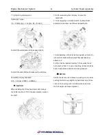
5. Install the cylinder head bolts. 

1) Tighten the eight cylinder head bolts on each bank, 

in several passes, in the sequence shown. 

Tightening Torque: 

1st step: 58.8N.m (6.0kgf.m, 43.4lbf-ft) 

2nd step: 90°± 2° 

3rd step: 120°± 2° 

  NOTICE 

Do not reuse the cylinder head bolts more than twice. 


6. Install the timing chain case bracket (A). Tighten the 

vertical-direction bolts slightly first and then the 

horizontal-direction ones and the vertical-direction 

ones with the specified torque below. 

Tightening Torque: 

19.6 ~ 25.5Nm (2.0 ~ 2.6kgf.m, 14.5 ~ 18.8lb-ft) 


Summary of Contents for S220P

Page 1: ...WORKSHOP MANUAL for S Engine Series Applicable to S250S S250P S250J S220S S220P model Service Department Technical Information Edition 1st ...

Page 2: ...S Engine Series 1 Engine Mechanical System Engine Mechanical System General Cooling System Timing System Cylinder Head Assembly Engine Block Lubrication System Intake and Exhaust System Coupling System ...

Page 3: ...Engine Mechanical System 2 General Information General Information Specifications ...

Page 4: ...Engine Mechanical System 3 General Information Specifications ...

Page 5: ...Engine Mechanical System 4 General Information Specifications ...

Page 6: ... 30 10 below Oil pressure at idle 0 8kg 7 85kPa 1 14psi Cooling system Cooling method Forced circulation with sea water pump Coolant quantity 12L 12 68US qt 10 56lmp qt Thermostat Type Wax pellet type Opening temperature 82 2 176 0 183 2 Lift 0 35mm 0 0138in Full opening temperature 92 197 6 Lift 10mm 0 3939in or more Turbochager EVGT cooling method Sea water cooling type Actuator Electrical Turbi...

Page 7: ...4 7 74 5 6 6 7 6 47 7 55 0 Timing chain tensioner lever bolt 19 6 23 5 2 0 2 4 14 5 17 4 Timing chain guide bolt 7 8 11 8 0 8 1 2 5 7 8 7 Damper pulley bolt 186 3 205 9 58 62 19 0 21 0 58 62 137 4 151 9 58 62 Alternator bracket 19 6 26 5 2 0 2 7 14 5 19 5 Alternator 29 4 41 2 3 0 4 2 21 7 30 4 Front chain cover bolt M6 7 8 11 8 0 8 1 2 5 8 8 7 Front chain cover bolt M8 19 6 25 5 2 0 2 6 14 5 18 8 ...

Page 8: ...4 5 2 5 18 1 Upper oil pan bolt 1 9 8 11 8 1 0 1 2 7 2 8 7 Upper oil pan bolt 2 29 4 33 3 3 0 3 4 21 7 24 6 Lower oil pan bolt 9 8 11 8 1 0 1 2 7 2 8 7 Oil pan drain plug 34 3 44 1 3 5 4 5 25 3 32 5 Oil screen bolt 14 7 21 6 1 5 2 2 10 8 15 9 Intake and exhaust system Inlet lower manifold assembly 9 8 11 8 1 0 1 2 7 2 8 7 Inlet upper manifold assembly 9 8 11 8 1 0 1 2 7 2 8 7 Turbocharger oil retu...

Page 9: ...speed of 220rpm or more 4 Repeat step 1 though 3 for each cylinder NOTICE This measurement must be done in as short a time as possible Compression pressure 2 745 85kPa 28 0kg cm 398 25psi 220 rpm Minimum pressure 2 255 52kPa 23 0kg cm 327 14psi 5 If the cylinder compression in 1 or more cylinders is low pour a small amount of engine oil into the cylinder through the spark plug hole and repeat step...

Page 10: ...Engine Mechanical System 9 Cooling System Special Service Tools ...

Page 11: ...Engine Mechanical System 10 Cooling System Special Service Tools ...

Page 12: ...Engine Mechanical System 11 Cooling System Cooling system Components 1 Heat exchanger assembly 5 Anode 2 Coolant pipe 6 Raw water hose 3 Coolant hose 7 Oil cooler assembly 4 Clamp 8 Sea water pump ...

Page 13: ...hanical System 12 Cooling System 1 Coolant Inlet fitting 6 Coolant pipe 2 Thermostat assembly 7 Coolant hose 3 Coolant outlet duct 8 Clamp 4 Coolant temp sensor 9 O ring 5 Coolant temp control assembly 10 Gasket ...

Page 14: ...TION Take CAUTION in order the direction of curved fan to be in the right direction when using the impeller 8 Reassemble aligning axis of impeller shaft and engine cam 9 Apply lubricant O rings on inserting parts and cover and assembly CAUTION Make sure you use new O ring after seawater pump reassemble 10 Tighten seawater pump with three bolts 11 Place hoses and clamps 12 Complete the reassembly a...

Page 15: ...e and dissemble power steering pump 2 Remove hoses and clamps connected to pumps 3 Unscrew three bolts fixing cooler Tightening torque 44 1 49 0Nm 4 5 5 0kgf m 32 5 36 2lb ft 4 Use L wrench and remove end cap on both sides 5 Remove tube bundle out of housing using soft hammer 6 Check the condition of O ring on both end cap 7 Check to see any sea water intake into oil cooler 8 Check the condition o...

Page 16: ...s in the reverse order of removal Water Outlet Duct and Fitting Water outlet and fitting 1 Remove the intake and the exhaust manifold system 2 Remove the water outlet duct A Tightening torque 9 8 11 8Nm 1 0 1 2kgf m 7 2 8 7lb ft 3 Loosen the oil cooler mounting bolts for space of the outlet fitting s removal 4 Remove the water outlet fitting A Tightening torque 9 8 11 8Nm 1 0 1 2kgf m 7 2 8 7lb ft...

Page 17: ...the MAX and MIN lines when the engine is cold If low check for leaks and add quality qualified engine coolant If you can t get any quality qualified coolant add similar high quality mono ethylene glycol based non silicate non amine non nitrite and non borate coolant or equivalent to MAX line Check Engine Coolant Quality 1 Wait until engine is cool and then carefully remove the cap 2 Check if there...

Page 18: ...Engine Mechanical System 17 Cooling System ...

Page 19: ...Engine Mechanical System 18 Cooling System Thermostat ...

Page 20: ...onents 1 Tensioner assembly 6 Water pump pulley flange 11 P S oil pump 2 Bracket tensioner 7 Water pump bearing 12 Alternator 3 Water pump pulley 8 Seal unit 13 Bracket alternator 4 Stay tensioner bracket 9 Water pump impeller 14 Drive belt 5 Water pump 10 Water pump gasket ...

Page 21: ...stem 1 Cap Assembly chain case 6 Lower head seal 11 Lower O ring 2 High pressure pump cover 7 Upper head seal 12 Hose assembly 3 Chain front cover 8 Chain oil jet 13 Chain case cap 4 Front oil seal 9 Chain case 5 Bolt guide 10 Upper O ring ...

Page 22: ...nsioner 6 Oil pump sprocket 11 Oil pump chain 2 Timing chain 7 Tensioner lever 12 Camshaft 3 Camshaft sprocket 8 Lower chain guide 13 Oil pump drive sprocket 4 High pressure pump sprocket 9 Upper chain guide 5 Crankshaft sprocket 10 Oil pump chain tensioner ...

Page 23: ...1 Compressing the tensioner with a wrench in a left hand by turning it clockwise start removing the drive belt from the water pump side idler NOTICE Conform to what is described above because tension of the belt in this engine is higher than ones of other engines for preventing a slip 2 Remove the drive belt tensioner A 3 Remove the power steering bracket 4 Remove the water pump pulley D 5 Remove ...

Page 24: ...chain cover A 13 Remove the hydraulic tensioner A 14 Remove the timing chain with the chain guide and the tensioner lever 15 Remove the high pressure fuel pump sprocket A 16 Remove the upper head seal 17 Remove the water pump A with its gasket 18 Remove the high pressure pump 19 Remove the chain case mounting bolts 20 Remove the chain case assembly C ...

Page 25: ...t 8 35 3 Install the water pump A with a new gasket Tightening Torque 9 8 11 8Nm 1 0 1 2kgf m 7 2 8 7lb ft 6 16 4 Install the high pressure pump 5 Applying sealant install the upper head seal 6 Install the high pressure fuel pump sprocket A Tightening Torque 64 7 74 5Nm 6 6 7 6kgf m 47 7 55 0lb ft 7 Install the timing chain B aligning the timing marks E on the camshaft sprocket C and the crankshaf...

Page 26: ... 1 2kgf m 7 2 8 7lb ft 11 Confirm that the timing marks are on the right position and remove the SST 00200 0T005 12 Applying sealant on the front chain cover sealing surface install the front chain cover within fifteen minutes Timing System 13 Tighten the front chain cover mounting bolts A 20EA B 4EA Tightening Torque 7 8 11 8Nm 0 8 1 2kgf m 5 8 8 7lb ft 20EA 19 6 25 5Nm 2 0 2 6kgf m 14 5 18 8lb f...

Page 27: ...starter and installing the SST 00200 0T007 tighten the crankshaft bolt 16 Install the drive belt idler A Tightening Torque 34 3 44 1Nm 3 5 4 5kgf m 25 3 32 5lb ft 17 Install the water pump A Tightening Torque 7 8 11 8Nm 0 8 1 2kgf m 5 8 8 7lb ft 18 Install the engine hanger Tightening Torque 19 6 26 5Nm 2 0 2 7kgf m 14 5 19 5lb ft 19 Install the alternator B with its bracket A Tightening Torque 29...

Page 28: ...dary O ring or oil 3 Check oil level after assembling the pump and supply oil gradually 4 Check the level of reserve tank 5 Complete the reassembly and start the ignition Then check any oil leakage out of shaft Replacement 24 Install the drive belt tensioner A Tightening Torque 72 6 84 3Nm 7 4 8 6kgf m 53 5 62 2lb ft upper 28 4 34 3Nm 2 9 3 5kgf m 21 0 25 3lb ft lower 25 Compressing the tensioner ...

Page 29: ... guide 2 Valve 8 Cylinder head gasket 14 Sealing cap 3 Valve spring 9 Cylinder head 15 Camshaft bearing ladder 4 Valve spring retainer lock 10 Valve spring upper retainer 16 Cylinder head cover 5 Water outlet fitting gasket 11 Hydraulic lash adjuster HLA 17 Camshaft position sensor CMP 6 Water outlet fitting 12 Cam follower 18 Engine hanger ...

Page 30: ... 29 Cylinder Head assembly 1 Water outlet fitting gasket 6 Sealing cap 2 Water outlet fitting 7 Camshaft bearing ladder 3 Water outlet fitting O ring 8 Cylinder head cover 4 Cylinder head gasket 9 Engine hanger 5 Cylinder head ...

Page 31: ...move the glow plug wiring 6 Remove the water outlet duct A 7 Remove the cylinder head cover A 8 Remove the camshaft bearing ladder A 9 Remove the sealing cap A from the cylinder head assembly 10 Remove the camshafts 11 Remove the HLA hydraulic lash adjuster A and the cam follower assembly B 1 After you removing it HLA shall be held upright so that oil in it should not spill and be assured that dus...

Page 32: ... NOTICE Do not reuse the cylinder head bolts more than twice 16 Remove the cylinder head quietly in order not to damage the gasket with the bottom part of the end 17 Remove the cylinder head gasket A 18 Remove the water outlet fitting A 19 Using the SST 00200 0T011 00200 0T010 compress the spring and remove the retainer locks 20 Remove the valve valve spring and spring retainer ...

Page 33: ...der head gasket 1 Measure the piston protrusion from the upper cylinder block face on the twelve places A F for each bank at TDC top dead center 2 Select the gasket in the table below using the average value of the six piston protrusions If an average value of a piston is over than the each rank limit use one rank thicker gasket than the specified one in the table below ...

Page 34: ...ON Put on a lid on the intake port or the water outlet fitting in order for some materials such as bolts not to get inside 5 Install the cylinder head bolts 1 Tighten the eight cylinder head bolts on each bank in several passes in the sequence shown Tightening Torque 1st step 58 8N m 6 0kgf m 43 4lbf ft 2nd step 90 2 3rd step 120 2 NOTICE Do not reuse the cylinder head bolts more than twice 6 Inst...

Page 35: ...nd play remove the camshafts 11 After applying oil install the HLA hydraulic lash adjuster A and the cam follower assembly B 1 Until installing HLA shall be held upright so that oil in it should not spill and be assured that dust does not adhere to it 2 HLA shall be inserted tenderly to the cylinder head not to spill oil from it In case of spilling air bent shall be done in accordance with the air...

Page 36: ...ft 14 pressing the exhaust camshafts take out the pin from their sprockets 15 Put the ladder gaskets A on the camshaft bearing ladder and apply sealant Also apply some oil on the contacting surface with the camshafts 16 Install the sealing caps A with applying sealant LOCTITE 5902 5900 or equivalent on the grooves 4 places at the circumference 17 Install the camshaft bearing ladder A with the sequ...

Page 37: ...8 11 8Nm 1 0 1 2kgf m 7 2 8 7lb ft 21 Install the glow plug wiring 22 Install the delivery pipe the injectors and the high pressure pipe 23 Install the intake and exhaust manifold 24 Install the timing chain 25 Install the drive belt NOTICE Thoroughly clean all parts to be assembled Before installing the parts apply fresh engine oil to all sliding and rotating surface Replace oil seals with new on...

Page 38: ...valve spring and spring retainer NOTICE Apply engine oil on the valves when installing 3 Using the SST 00200 0T011 00200 0T010 compress the spring and install the retainer locks After installing the valves ensure that the retainer locks are correctly in place before releasing the valve spring compressor 4 Lightly tap the end of each valve stem two or three times with the wooden handle of a hammer ...

Page 39: ...Connecting rod 13 Oil ring 2 Crankshaft assembly 8 Connecting rod 14 Snap ring 3 Bed plate 9 Piston 15 Crankshaft key 4 Flywheel sub assembly 10 Piston pin 16 Damper pulley 5 Flywheel adapter 11 No 1 piston ring 17 Washer 6 Cylinder Block 12 No 2 piston ring 18 Engine supt brkt RH 19 Engine supt brkt LH ...

Page 40: ...cting rod and the cap with its bearings together Arrange the piston and connecting rod assemblies in the correct order 3 Remove the piston and connecting rod assembly Using a press machine remove the piston pin from the piston 4 Remove the piston rings NOTICE Arrange the piston rings in its order having an eye to the Y mark on the ring which tells you it is the upper side 5 Remove the flywheel and...

Page 41: ...Reassemble the lower bearings and the connecting rod caps and tighten the bolts with the specified torque below Tightening Torque 27 5 31 4Nm 2 8 3 2kgf m 20 3 23 1lb ft 88 92 NOTICE Do not rotate the crankshaft Do not reuse the connecting rod cap bolts 7 Remove the connecting rod cap again 8 Measure the plastic gauge at its widest point 9 If the measurement from the plastic gauge is out of the sp...

Page 42: ...he marks are indecipherable because of an accumulation of dirt or dust do not scrub them with a wire brush or scraper Clean them only with solvent or detergent Connecting rod mark location Discrimination Of Connecting Rod Crankshaft pin journal mark location Discrimination Of Crankshaft Pin Journal Connecting Rod Bearing Mark Location Discrimination Of Connecting Rod Upper Bearing Discrimination o...

Page 43: ...o journal oil clearance remove the bed plate and lower bearings 2 Clean each main journal and lower bearing with a clean shop towel 3 Place one strip of plastic gauge across each main journal 4 Reinstall the lower bearings and bed plate and then tighten the bolts NOTICE Reinstall the lower bearings and bed plate and then tighten the bolts If the bed plate bolts are damaged or deformed replace them...

Page 44: ... gauge shows the clearance is still incorrect try the larger or smaller bearing Recheck the oil clearance NOTICE If the proper clearance cannot be obtained by using the appropriate larger or smaller bearings replace the crankshaft and start the measurement from the first CAUTION If the marks are indecipherable because of an accumulation of dirt and dust do not scrub them with a wire brush or scrap...

Page 45: ...lection Table 2 Check the crankshaft end play Using a dial indicator measure the clearance while prying the crankshaft back and forth End play Standard 0 1 0 3mm 0 0039 0 118in 3 Inspect the crankshaft main journals and pin journals Using a micrometer measure the diameter of each main journal and pin journal Main journal diameter 75 982 76 000mm 2 9914 2 9921in Pin journal diameter 63 482 63 500mm...

Page 46: ...asket surface Less than 0 05mm 0 0020in Less than 0 042mm 0 0017in for width Less than 0 096mm 0 0038in for length Less than 0 012mm 0 0005in for 50mm 50mm 4 Inspect the cylinder bore Visually check the cylinder for vertical scratch If deep scratch is present replace the cylinder block 5 Inspect the cylinder bore diameter Using a cylinder bore gauge measure the cylinder bore diameter at position i...

Page 47: ...e rise during honing bore the cylinder holes in the firing order 5 Hone the cylinders finishing them to the proper dimension piston outside diameter gap with cylinder 6 Check the clearance between the piston and cylinder Piston to cylinder clearance 0 064 0 084mm 0 0025 0 0033in NOTICE When boring the cylinders finish all of the cylinders to the same oversize Do not bore only one cylinder to the o...

Page 48: ... cylinder bore Position the ring at right angles to the cylinder wall by gently pressing it down with a piston Measure the gap with a feeler gauge If the gap exceeds the service limit replace the piston rings If the gap is too large recheck the Cylinder bore inner diameter If the bore is over the service limit the cylinder block must be re boring Piston ring end gap No 1 0 20 0 35mm 0 0079 0 0138i...

Page 49: ...gs have the oil grooves of the oil holes The lower ones do not 1 Aligning the bearing claw with the groove of the cylinder block push in the four upper bearings A Apply oil on the bearings at this moment 3 Place the crankshaft A on the cylinder block 4 Aligning the bearing claw with the groove of the bedplate push in the four lower bearings A Apply oil on the bearings at this moment 5 Place the be...

Page 50: ... 7Nm 6 3 6 7kgf m 45 6 48 5lb ft 1st step 120 124 2nd step 3 Loosen the bolts No 18 20 and 21 4 Tighten the No 17 25 bolts with the specified torque below Tightening Torque 29 4 33 3Nm 3 0 3 4kgf m 21 7 24 6lb ft 1 st step 5 Check that the crankshaft rotates smoothly 7 Check the crankshaft end play using a dial indicator End play Standard 0 1 0 3mm 0 0039 0 118in 8 Using the SST 00200 0T013 00200 ...

Page 51: ...ston pin hole 2 Apply sufficient engine oil or non water soluble press oil to outer surface of the piston inner surface of piston pin hole and small end bore of the connecting rod before inserting the piston pin 3 Insert the piston pin into the piston pin hose and the small end bore of connecting rod after setting the piston front marks A and the RH LH marks B of the connecting rod facing to the t...

Page 52: ...pushing the piston into place again Be careful for the oil jets not to be damaged by the connecting rods in this step 4 Apply engine oil to the bolt threads Install the rod caps with bearings and tighten the bolts Tightening Torque 27 5 31 4Nm 2 8 3 2kgf m 20 3 23 1lb ft 88 92 NOTICE Maintain downward force on the ring compressor to prevent the rings from expending before entering the cylinder bor...

Page 53: ...2 Lubrication System Lubrication System Components 1 Upper oil pan 5 Hose oil outlet 9 Washer Plain 2 Lower oil pan 6 Hose oil inlet 10 Joint I 3 Oil level gauge assembly 7 Ear Clamp 11 Q connector 4 Oil extraction pump 8 Bolt I ...

Page 54: ...Engine Mechanical System 53 Lubrication System 1 Oil filter assembly 3 Oil pressure sensor 2 Oil cooler assembly 4 Rear oil seal ...

Page 55: ...Engine Mechanical System 54 Lubrication System ...

Page 56: ...il filter paper is removed with its cap at this moment 2 Remove the oil filter paper A and its O ring B from its cap 1 Remove the filter paper assembly A 2 Replace the filter paper assembly and O ring B with new ones and do not reuse the O ring removed 3 Assemble the oil filter cap with the filter fixed Tightening Torque 24 5Nm 2 5kgf m 18 1lb ft 4 Opening the oil filler cap and removing the oil p...

Page 57: ... types of operation select only those lubricants which 1 Satisfy the requirement of the API or ACEA classification 2 Have proper SAE grade number for expected ambient temperature range 3 Lubricants that do not have both an SAE grade number and API service classification on the container should not be used ...

Page 58: ... 2 Install the oil pump and screen assembly with the specified torque Tightening Torque 19 6 26 5Nm 2 0 2 7kgf m 14 5 19 5lb ft 3 Check if the oil pump works properly 4 With the cylinder block bed plate crankshaft piston assembly connecting rod assembly and the oil pump assembly installed insert the crankshaft sprocket A in the crankshaft aligning the No 1 piston at the BDC bottom dead center 5 In...

Page 59: ...own as below Liquid gasket LOCTITE 5900 or equivalent NOTICE Apply sealant cautiously to prevent sealant from coming in the oil pan during installation After applying sealant assemble the oil pan in fifteen minutes 5 Tighten the mounting bolts with the order and the specified torque below Tightening Torque 9 8 11 8Nm 1 0 1 2kgf m 7 2 8 7lb ft all bolts except 20 21 29 4 33 3Nm 3 0 3 4kgf m 21 7 24...

Page 60: ... the order and the specified torque below Tightening Torque 9 8 11 8Nm 1 0 1 2kgf m 7 2 8 7lb ft Oil Filter And Cooler Assembly 1 Assemble the oil cooler B to the oil filter A 2 Install the oil filter and cooler assembly to the cylinder block 3 Check if there is rubber packing between the oil filter and the block or the oil cooler If so apply Engine oil Tightening Torque 19 6 26 5Nm 2 0 2 7kgf m 1...

Page 61: ...Engine Mechanical System 60 Intake and Exhaust System Intake and Exhaust System Inter cooler Component 1 Intercooler hose 4 Intercooler pipe 2 Intercooler assembly 5 Anode 3 Clamp ...

Page 62: ... Intake Manifold Components 1 Gasket Rubber Upper 6 Boost Pressure sensor 2 Manifold assembly Inlet lower 7 Gasket Pipe 3 Manifold assembly Inlet Upper 8 Bracket Intake manifold 4 Adaptor Boost pressure sensor 9 Gasket Intake manifold 5 O Ring 10 Adapter ...

Page 63: ...N avoid intercooler fin damage 10 Clean housing and intercooler and heat exchanger into housing 11 Install new O ring 12 Check the direction of end cap on both sides for assembly 13 Install new anode Intake Manifold 1 Remove the inlet upper manifold assembly 2 Remove the glow control unit A 3 Remove the CMP sensor 4 Remove the fuel feed and return hose or pipe 5 Remove the high pressure fuel pipe ...

Page 64: ...1 Install the inlet manifold gaskets A 2 Install the inlet lower manifold assembly A CAUTION The inlet lower manifold assembly A is the assembly including the swirl control actuator B If you have already disassembled the swirl control actuator from the inlet lower manifold you should throw them away and install a new inlet lower manifold assembly including the swirl control actuator Disassembly an...

Page 65: ...pump Tightening Torque 7 8 11 8Nm 0 8 1 2kgf m 5 8 8 7lb ft 10 Install the engine hanger Tightening Torque 19 6 26 5Nm 2 0 2 7kgf m 14 5 19 5lb ft 11 Install the high pressure fuel pipe rail to rail 12 Install the fuel feed and return hose or pipe Tightening Torque 9 8 11 8Nm 1 0 1 2kgf m 7 2 8 7lb ft 13 Install the CMP sensor Tightening Torque 9 8 11 8Nm 1 0 1 2kgf m 7 2 8 7lb ft 14 Install the g...

Page 66: ...nt 1 Gasket Turbocharger outlet 6 Gasket Exhaust manifold 11 Clamp Bellows 2 Exhaust pipe 7 Exhaust elbow 12 Bracket Exhaust elbow 3 Gasket Exhaust pipe 8 Exhaust pipe 13 Heat Protector Ex pipe LH 4 Exhaust manifold LH 9 Bellows 5 Exhaust manifold RH 10 Heat protector Ex pipe RH ...

Page 67: ...stem 66 Intake and Exhaust System Turbocharger TC Component 1 Turbo charger 6 I bolt joint 2 Pipe oil return 7 Nut Oil feed pipe 3 Gasket 8 Exhaust pipe 4 O Ring 9 Gasket T C oil drain 5 Pipe Oil feed 10 Heat protector T C ...

Page 68: ...r for reassembly 7 Remove the oil return pipe bolts A Tightening Torque 9 8 11 8Nm 1 0 1 2kgf m 7 2 8 7lb ft 8 Remove the oil feed pipe and the blow by hose C Tightening Torque 18 6 25 5Nm 1 9 2 6kgf m 13 7 18 8lb ft oil feed pipe nut A 26 5 32 4Nm 2 7 3 3kgf m 19 5 23 9lb ft oil feed pipe eye bolt B 9 8 11 8Nm 1 0 1 2kgf m 7 2 8 7lb ft oil feed pipe mounting bolt D WARNING When install the turboc...

Page 69: ... remove manifold CAUTION Contacts with exhaust manifold after engine operation may cause serious injury when manifold has not cooled off 12 Installation is in the reverse order of removal 13 Check to see possible engine coolant and exhaust emission leakage after manifold reassembly ...

Page 70: ...sing 3 Loosen 6 bolts Remove coupling WaterJet 1 Loosen 12 bolts 2 Loosen 2 nuts Remove housing 3 Loosen 6 bolts Remove coupling Shaft Drive 1 Loosen 12 bolts 2 Loosen 2 nuts Remove housing 3 Loosen 6 bolts Remove coupling Tightening Torque M8 24 5 29 4Nm 2 5 3 0kgf m 18 1 21 7lb ft M10 44 1 49 0Nm 4 5 5 0kgf m 32 5 36 2lb ft M12 63 7 68 6Nm 6 5 7kgf m 47 0 50 6lb ft ...

Page 71: ...S Engine Series 70 Engine Electrical System Engine Electrical System General Charging System Starting System Preheating System ...

Page 72: ...formation General information Specifications Charging system Starting system Items Specification Starter Rated voltage 12V 2 2kW No of pinion teeth 10 No load characteristics Voltage 11V Ampere 130A MAX Speed 3 600 rpm MIN Preheating system ...

Page 73: ...Engine Electrical System 72 General Information Troubleshooting Charging system ...

Page 74: ...Engine Electrical System 73 General Information Starting system Special service tools ...

Page 75: ...Engine Electrical System 74 Charging System Charging system Alternator ...

Page 76: ... wrench remove the drive belt 4 Remove the tow alternator mounting bolts 3 0 4 2 kgf m 5 Installation is in the reverse order of removal Disassembly 1 Remove the rear cover nut A 2 Remove the alternator cover A using a screw Drive B 3 Loosen the mounting bolts A and disconnect the brush holder assembly B 4 Remove the slip ring guide A 5 Remove the pulley A using the SST 00200 0T017 ...

Page 77: ...eck that there is continuity between the slip Rings A 2 Check that there is no continuity between the Slip rings and the rotor B or rotor shaft C 3 If the rotor fails either continuity check replace the alternator Stator 1 Check that is continuity between each pair of leads A 2 Check that there is no continuity between each lead and the coil core 3 If the coil fails either continuity check replace...

Page 78: ...ged overrunning clutch 3 Check the battery condition Check electrical connections at the battery battery negative cable connected to the body engine ground cables and the starter for looseness and corrosion Then try starting the engine again If the starter cranks normally the engine repairing the loose connection repaired the problem The starting system is now OK If the starter still does not cran...

Page 79: ...oved out the hold in coil of the solenoid is working properly If the pinion moves in replace the solenoid Free Running Test 1 Place the starter motor in a vise equipped with soft jaws and connect a fully charged 12 volt battery to starter motor as follows 2 Connect a test ammeter 100 ampere scale and carbon pile rheostats shown is the illustration 3 Connect a voltmeter 15 volt scale across starter...

Page 80: ...Engine Electrical System 79 Starting System Components ...

Page 81: ...for wear or damage from contact with the permanent magnet If there is wear or damage replace the armature 4 Check the commutator A surface If the surface is dirty or burnt resurface with emery cloth or a lathe within the following specifications or recondition with 500 or 600 sandpaper B 5 Check the commutator diameter If the diameter is below the service limit replace the armature Standard New 30...

Page 82: ...gments The undercut should not be too shallow too narrow or v shaped D Commutator mica depth Standard New 0 5 mm 0 0197 in Limit 0 2mm 0 0079 in 8 Check for continuity between the segments of the commutator If an open circuit exists between any segments replace the armature 9 Check with an ohmmeter that no continuity exists between the commutator A and armature coil core B and between the commutat...

Page 83: ...tion of the flywheel or torque converter ring gear if the starter drive gear teeth are damaged Cleaning 1 Do not immerse parts in cleaning solvent Immersing the yoke assembly and or armature will damage the insulation wipe these parts with a cloth only 2 Do not immerse the drive unit in cleaning solvent The overrun clutch is pre lubricated at the factory and sol vent will wash lubrication from the...

Page 84: ...to 1000 within 2 3sec so that starting performance is reached as same level as gasoline In addition it is realized that consumption of electricity is optimized by PWM control Inspection Conditions before inspection Battery voltage 12V Cooling water temperature Below 30 86 F Disconnect the water temperature sensor connector 1 Connect voltmeter between glow plug plate and plug body ground 2 Check in...

Page 85: ...ction The specified electrical data below are related to the nominal voltage and to an ambient temperature of 22 5 23 5 72 5 74 3 on new glow plugs Current Consumption Initial current at 11V less than 27 0A Operating current after 5 sec less than 9 0A Operating current after 60 sec less than 8 0A Cold Resistance The measured values are valid for 4 minutes at nominal voltage or for 10 minutes at 98...

Page 86: ...Engine Electrical System 85 Preheating System Preheating time before starting Preheating time after starting Schematic diagram ...

Page 87: ...S Engine Series 86 Fuel System Fuel System General Diesel Control System Fuel Delivery System DTC Diagnosis Trouble Code ...

Page 88: ...ilt in engine room High Pressure Fuel Pump Type Mechanical Plunger pumping type Driven by Timing chain Low Pressure Fuel Pump Type Electrical Driven by Electric motor Sensor Boost Pressure Sensor BPS Type Piezo resistive pressure sensor type Specification Intake Air Temperature Sensor IAT Built in Air Filter Type Thermistor type Specification Engine Coolant Temperature Sensor ECTS Type Thermistor ...

Page 89: ...nsor type Specification Fuel Temperature sensor FTS Type Thermistor type Specification Accelerator Position Sensor APS Type Potentiometer type Specification Water sensor Specification Actuators Injector Type Piezo injector Specification Fuel Pressure Regulator Valve Specification Rail Pressure Regulator Valve Specification Electric VGT Control Actuator Type DC motor driven ...

Page 90: ...6 9 10 8 0 7 1 1 5 1 8 0 Glow plug installation bolt 7 8 10 8 0 8 1 1 5 8 8 0 Fuel Delivery System Item N m Kgf m lb ft Low pressure fuel pump installation bolts 39 2 44 1 4 0 4 5 28 9 32 5 Injector clamp installation bolts 24 5 26 5 2 5 2 7 18 1 19 5 High pressure fuel pump installation bolts 24 5 34 3 2 5 3 5 18 1 25 3 Common rail Bank1 installation bolts 19 6 26 5 2 0 2 7 14 5 19 5 Common rail ...

Page 91: ...Fuel System 90 General Information Special Service Tools ...

Page 92: ...eze Frame Data Connect G Scan to Diagnostic Link Connector Never erase DTC and freeze frame data before completing step 2 MIL DTC in Problem Analysis Sheet 4 Inspect engine Visually Go to step 9 if you recognize the problem 5 Recreate Simulate Symptoms of the DTC 6 Confirm Symptoms of Problem 7 Recreate Simulate Symptom 8 Check the DTC 9 Perform troubleshooting procedure for DTC 10 Adjust or repai...

Page 93: ...ment Problem frequency Constant Sometimes Once only Other Weather Fine Cloudy Rainy Snowy Other Temperature Approx Other Place Sea Lake Other Engine operation Starting Just after starting Idling Driving Constant speed Deceleration Other 4 MIL DTC Alarm MIL Malfunction Indicator Lamp ON Sometimes lights up OFF Other Alarm ON Sometimes OFF Other DTC DTC NO Freeze Frame Date ...

Page 94: ...ed pins and then verify that the connectors are always securely fastened 3 Slightly shake the connector and wiring harness vertically and horizontally 4 Repair or replace the component that has a problem 5 Verify that the problem has disappeared with the road test Simulating Vibration a Sensors and Actuators Slightly vibrate sensors actuators or relays with finger WARNING Strong vibration may brea...

Page 95: ...f connectors cannot be accessed from harness side NOTICE Use a fine wire to prevent damage to the terminal Do not damage the terminal when inserting the tester lead 2 Checking Point for Connector a While the connector is connected Hold the connector check connecting condition and locking efficiency b When the connector is disconnected Check missed terminal crimped terminal or broken core wire by s...

Page 96: ...tween the wire harness and any installed part 6 If the covering of wire harness is damaged secure repair or replace the harness Electrical Circuit Inspection Procedure 1 Procedures for Open Circuit Continuity Check Voltage Check If an open circuit occurs as seen in FIG 1 it can be found by performing Step 2 Continuity Check Method or Step 3 Voltage Check Method as shown Below 2 Continuity Check Me...

Page 97: ...ethod for Short to Ground Circuit Continuity Check with Chassis Ground If short to ground circuit occurs as shown in FIG 5 the broken point can be found by performing Step 2 Continuity Check Method with Chassis Ground as shown below 2 Continuity Check Method with Chassis Ground NOTICE Lightly shake the wire harness above and below or from side to side when measuring the resistance Specification Re...

Page 98: ...r less The short to ground circuit is between terminal 1 of connector C and terminal 1 of connector B1 Actuation test Items Test Condition MIL ENGINE CHECK ACTUATION TEST IG ON ENGINE RUN FUEL PUMP RELAY ACTUATION TEST IG ON ENGINE RUN ELECTRIC VGT CONTROL ACTUATOR ACTUATION TEST IG ON ENGINE RUN FUEL PRESSURE REGULATOR VALVE HP PUMP SIDE ACTUATION TEST IG ON ENGINE RUN RAIL PRESSURE REGURATOR VAL...

Page 99: ...dual injector not adapted No engine coolant temperature sensor signal No rail pressure sensor signal Low battery voltage Fuel pressure regulator valve contaminated stuck jammed Rail pressure regulator valve contaminated stuck jammed Bad fuel quality or water ingress in fuel Inversion of fuel connections feed return Clogged low pressure fuel circuit Clogged fuel filter Oil level too high or too low...

Page 100: ...oltage regulator ECM program error or hardware fault SYMPTOM 6 BLUE WHITE OR BLACK SMOKES Compensation of individual injector not adapted No engine coolant temperature sensor signal No rail pressure sensor signal Fuel pressure regulator valve contaminated stuck jammed Rail pressure regulator valve contaminated stuck jammed Oil level too high or too low Bad fuel quality or water ingress in fuel Clo...

Page 101: ...taminated stuck jammed Injector needle stuck injection possible over a certain pressure ECM program error or hardware fault SYMPTOM 11 ENGINE STOP Not connected fuel feed line Leakage in high pressure fuel circuit Fuse out of order Bad fuel quality or water ingress in fuel Clogged low pressure fuel circuit Clogged fuel filter Crank signals missing Fuel pressure regulator valve contaminated stuck j...

Page 102: ...ture too high SYMPTOM 14 TOO MUCH POWER Compensation of individual injector not adapted Oil suction engine racing ECM program error or hardware fault SYMPTOM 15 EXCESSIVE FUEL CONSUMPTION Not connected fuel return line at injector Leakage at the Fuel pressure regulator valve Leakage at fuel temperature sensor Leakage in high pressure fuel circuit Leakage in intake system Clogged air filter Compens...

Page 103: ...ature sensor Leakage at the space Leakage in high pressure fuel circuit SYMPTOM 19 THE ENGINE COLLAPSES AT TAKE Blocked accelerator pedal position sensor Incorrect state of the electrical pack devices Clogged air filter Inversion of fuel connections feed return Faulty fuel filter Bad fuel quality or water ingress in fuel Air ingress in the low pressure fuel circuit Clogged fuel filter Intermittent...

Page 104: ...tor is disconnected with the ignition switch turned on the diagnostic trouble code DTC is recorded In this case disconnect the battery negative terminal for 15 seconds or more and the diagnosis memory will be erased Checking Procedure Self diagnosis NOTICE When battery voltage is excessively low diagnostic trouble codes can not be read Be sure to check the battery for voltage and the charging syst...

Page 105: ...ank Sterndrive Model 8 Shift Plate Sterndrive Model 9 Main Fuel Filter with Water Detection Sensor 10 T M Oil Cooler or P STRG Oil Cooler 11 Cabin Heater Connector 12 BPS IATS 1 E VGT Heat Protector 2 Exhaust Elbow 3 Bell Housing Sterndrive Model 4 Drive Coupler Sterndrive Model 5 Engine Oil Exchange Button 6 Engine Emergency Stop Button 7 P STRG Oil Reservoir Tank Sterndrive Model 8 Shift Plate S...

Page 106: ...ature Sensor IATS 2 signal input Idle Analog 0 5 4 5V 10 Fuel Temperature Sensor FTS signal input IG ON Analog 0 5 4 5V 16 Injector Cylinder 2 High control output Engine run DC 17 Injector Cylinder 4 High control output 18 Injector Cylinder 6 High control output 20 Electric VGT Control Actuator control output IG ON PWM 250Hz Engine running duty 20 80 21 Sensor ground Always DC 0 0 5V 22 Engine Coo...

Page 107: ...r 5V IG ON DC 4 9 5 1V 52 Position Sensor signal input Idle DC 0 5 4 5V 54 Sensor power 5V IG ON DC 4 9 5 1V 55 Sensor ground Always DC 0 0 5V 56 Sensor ground Always DC 0 0 5V 57 Sensor shield 58 Crankshaft Position Sensor CKPS signal input Engine Run SINE Wave Vp_p Min 0V Connector CSD K 1 2 Power ground Always DC 0 0 5V 3 Battery power IG ON DC Battery Voltage 4 Power ground Always DC 0 0 5V 5 ...

Page 108: ...attery cable 2 Remove the cover of the ECM relay box 3 Disconnect the ECM connector 4 Install a new ECM ECM Problem Inspection Procedure 1 TEST ECM GROUND CIRCUIT Measure resistance between ECM and chassis ground using the backside of ECM harness connector as ECM side check point If the problem is found repair it 2 TEST ECM CONNECTOR Disconnect the ECM connector and visually check the ground termi...

Page 109: ...1 L B 1 2 FUEL_PUMP S2 S1 L B M 85 86 87 30 1 2 OIL_EXTRACTION _PUMP 1 2 3 4 5 6 7 8 ENG_MAIN11 MAIN_ENG12 7 3 2 1 4 7 3 2 1 4 OIL_PRESSURE _SNSR 1 6 6 8 8 9 23 GND 2 ALTERNATOR B 1 10 MAIN RLY POWER MRP 5 49 3 F_FILTER_RLY 9 10 THERMO_SW 2 1 GND F_FILTER_HTR 2 1 GND GND OIL_PUMP_SWITCH GND FUSE BOX L to GCU 5A IGNITION 30A SYSTEM POWER 15A M RELAY POWER 20A ECM POWER 30A FUEL HRT MRP MRP 85 86 87...

Page 110: ... E_VGT_ACTR 1 2 DIAGNOSIS 2 3 4 9 11 6 ENG_MAIN11 MAIN_ENG12 10 9 13 12 14 10 9 15 13 12 14 ENG_MAIN11 MAIN_ENG12 5 5 1 WATER_SNSR 3 2 1 2 FUEL_PRESSURE _REGULATOR TEMP_SNSR 1 3 4 4 39 10 INJ_1 3 5 CAM_EXTN 7 8 9 10 3 4 5 1 2 31 32 33 48 54 29 28 46 47 COOLANT_TEMP _SNSR 3 2 1 21 22 FUEL_PRESSURE _REGULATOR RAIL 2 1 5 42 GND 35 36 72 3 4 90 ECU_A20 GND 4 15 19 2 VARIABLE_SWIRL_ACTR 3 4 5 1 2 ECU M...

Page 111: ...0 Rail Pressure Sensor RPS signal input 41 Boost Pressure Sensor BPS signal input 43 Crankshaft Position Sensor CKPS signal input 46 Injector Cylinder 1 Low control output 47 Injector Cylinder 3 Low control output 48 Injector Cylinder 5 Low control output 49 VSA motor control output 50 VSA motor control output 51 Sensor power 5V 52 Position Sensor signal input 54 Sensor power 5V 55 Sensor ground 5...

Page 112: ...Fuel System 111 Diesel Control System EOI Engine Operating Indicator System Circuit Diagram 1 ...

Page 113: ...n relay power 3 Permanent power 4 Not used 5 Not used 6 Coolant temperature signal 7 Not used 8 Check lamp 9 Oil pressure signal 10 Gnd 11 Not used 12 Water detection signal 13 RPM signal 14 Not used 15 Not used 16 Not used 17 Neutral signal 18 K line 19 CAN_L 20 Changing signal 21 CAN_H 22 Not used 23 Gnd 24 Not used Connector EOI ...

Page 114: ...rminal from the battery and wait for about 30 seconds Components The injectors are installed on the cylinder head and inject the compressed fuel stored in common rail into each cylinder by ECM control signal This consists of the piezo actuator the hydraulic coupler which amplifies output of the piezo actuator the pressure control valve which moves the needle the needle which opens or closes the in...

Page 115: ...and this length is Stroke The number and the cross section of the ceramic are proportional to the actuator s stroke and output respectively HYDRAULIC COUPLER The hydraulic coupler is located under the piezo actuator and amplifies the actuator s output by the cross section ratio of the upper and the lower pistons At this time the actuator s stroke is lengthened The hydraulic oil is the fuel and the...

Page 116: ...RE CONTROL VALVE The Pressure Control Valve is located under the hydraulic coupler and controls the needle by amplified actuator s output NEEDLE The needle is located under the pressure control valve and finally opens or closes the injection hole ...

Page 117: ...Fuel System 116 Diesel Control System Specification Circuit Diagram ...

Page 118: ...njector tube or hose remove the protect cap attached on them Do not remove injector except for special case When installing Injector Wash the contact area of the injector and replace the O ring with a new one Spread oil on the injector O ring To protect damage caused by shock vertically insert the injector into the cylinder head When installing High Pressure Fuel Pipe Do not use again the used hig...

Page 119: ...ector NOTICE If the injector adheres to the cylinder head use the Special Service Tool SST No 00200 0T014 Installation 1 Installation is reverse of removal NOTICE 1 When installing the high pressure fuel pipe apply the specified tightening torques with the special service tool SST No 00200 0T015 2 When installing the high pressure fuel pipe connecting the common rail and injector follow the below ...

Page 120: ...Turn ignition switch OFF 2 Connect a scan tool to Data Link Connector DLC 3 Turn ignition switch ON 4 Perform the test in accordance with the message NOTICE The injector in cylinder with significantly high low idle speed injects more less quantity than the other injectors INJECTION QUANTITY COMPARISON 1 Turn ignition switch OFF 2 Connect a scan tool to Data Link Connector DLC 3 Turn ignition switc...

Page 121: ...TS 2 Function And Operation Principle The Boost Pressure Sensor BPS is installed on the intercooler assembly and measures the pressure of the compressed air in turbocharger By using this signal the ECM controls the Variable Geometry Turbocharger VGT Specification ...

Page 122: ...ystem Intake Air Temperature Sensor IATS 1 Intake Air Temperature Sensor IATS uses a Negative Temperature Characteristics NTC thermistor and senses intake air temperature Two intake air temperature sensors are installed in this engine ...

Page 123: ... coolant passage of the cylinder for detecting the engine coolant temperature The ECTS uses a thermistor which resistance is in inverse proportion to the temperature NTC Negative Temperature Coefficient During cold engine operation the ECM adjusts the injection amount and the timing by using this ECTS output signal to avoid engine stalling and improve drivability Specification ...

Page 124: ...tch OFF 2 Disconnect the engine coolant temperature sensor connector 3 Remove the sensor 4 After immersing the thermistor of the sensor into engine coolant measure resistance between ECTS signal terminal and ground terminal 5 Check that the resistance is within the specification ...

Page 125: ...shaft position This is a hall sensor and has a hall effect IC which output voltage changes when magnetic field is made on the IC with current flow It is related with Crankshaft Position Sensor CKPS and detects the piston position of the each cylinder which the CKPS can t detect By using this signal the ECM perceives the position of each cylinder and controls sequential injection Specification ...

Page 126: ...ion And Operation Principle The Crankshaft Position Sensor CKPS is installed on the flywheel housing and detects the crankshaft position By using this signal the ECM can calculate the piston position of each cylinder and the engine speed for sequential injection Specification ...

Page 127: ... APS is installed on the accelerator pedal assembly and consists of the two potentiometers which have independent circuit power signal output and ground individually This system makes the ECM recognize the driver s intention even if one sensor is broken Also the ECM can diagnose the sensor by comparing the two sensor s signal Specification ...

Page 128: ...aneous fuel pressure in the common rail The sensing element semiconductor device built in the sensor converts the pressure to voltage signal By using this signal the ECM can control correct injection amount and timing And it adjusts the rail pressure with the rail pressure regulator valve if the target pressure and the actual pressure calculated by the RPS output signal are different Specification...

Page 129: ...e fuel tank via fuel filter The FTS uses a thermistor which resistance is in inverse proportion to the temperature NTC Negative Temperature Coefficient With this signal the ECM can adjust the injection amount At high temperature vapor lock in fuel line or oil membrane destruction may appear Especially oil membrane destruction deteriorates fuel s lubrication performance and it may damage the high p...

Page 130: ...alled on high pressure pump and common rail bank 2 respectively These valves control fuel inlet feed from fuel tank via fuel filter and outlet return to fuel tank of high pressure fuel circuit This system is called Dual Fuel Pressure Control System and can precisely and quickly control the fuel pressure in accordance with various engine conditions by controlling the fuel inlet and outlet simultane...

Page 131: ...on high pressure pump and common rail bank 2 respectively These valves control fuel inlet feed from fuel tank via fuel filter and outlet return to fuel tank of high pressure fuel circuit This system is called Dual Fuel Pressure Control System and can precisely and quickly control the fuel pressure in accordance with various engine conditions by controlling the fuel inlet and outlet simultaneously ...

Page 132: ...lled on bottom end of fuel filter and detects presence of water in fuel When the water amount reaches the predetermined level the sensor sends the warning signal to the ECM NOTICE Without presence of water the lamp should flash for 2 seconds and turn off afterward in order that this system has normal condition ...

Page 133: ...otor which actuates the vane a 2 step gear which increases torque of the DC motor a position sensor which detects status of the vane an electric control unit which drives the DC motor and a reset spring which resets the de energized vane to its open position CAUTION After replacing the Electric VGT Control Actuator MUST perform the COMPONENT CHANGE ROUTINE procedure Refer to REPLACEMENT procedure ...

Page 134: ...igh Pressure Fuel Pipe Common Rail Injector 3 High Pressure Fuel Pipe Common Rail Common Rail 4 Fuel Feed Tube Fuel Filter High Pressure Fuel Pump 5 Fuel Return Tube High Pressure Fuel Pump Fuel Tank 6 Fuel Return Tube Common Rail Fuel Tank 7 Fuel Return Tube Injector Bank 1 Fuel Filter 8 Fuel Return Tube Injector Bank 2 Fuel Filter ...

Page 135: ... High Pressure Fuel Pump The high pressure fuel pump compresses fuel up to 1 600 bar and delivers the compressed fuel to the common rail Common Rail The two common rails are installed on bank 1 and 2 and are connected with the high pressure fuel pump and the injectors by the high pressure fuel pipes This rail stores the fuel compressed in the high pressure fuel pump So that the two rails have same...

Page 136: ...sensor connector the heater connector and the thermostat connector 3 Disconnect the fuel inlet tube quick connector and the fuel outlet tube quick connector 4 Disconnect the injector return tube quick connector 5 Unscrew the fuel filter bracket installation nuts and then remove the fuel filter from the engine Installation 1 Installation is reverse of removal ...

Page 137: ...ignition switch OFF and disconnect the negative battery cable 2 Remove the inlet upper manifold assembly A 3 Disconnect the fuel pressure regulator valve fuel temperature sensor connector A 4 Disconnect the fuel inlet tube quick connector A and the fuel return tube quick connector B ...

Page 138: ...0 0T016 on the sprocket with the bolts A SST No 00200 0T016 13 Push the pump shaft from the sprocket with rotating the main bolt C SST No 00200 0T016 clockwise and then remove the high pressure fuel pump from the engine Installation 1 Installation is reverse of removal NOTICE When installing the high pressure fuel pipe apply the specified tightening torques with the special service tool SST No 002...

Page 139: ...orm any work on injection system with engine running or within 30 seconds after the engine stops Keep cleanly the parts and the working area Pay attention to a foreign substance Just before installing injector tube or hose remove the protect cap attached on them Do not remove injector except for special case When installing Injector Wash the contact area of the injector and replace the O ring with...

Page 140: ... 5 Remove the high pressure fuel pipes D E 6 Unscrew the mounting bolts F and then remove the common rail from the engine Installation 1 Installation is reverse of removal NOTICE 1 When installing the high pressure fuel pipe apply the specified tightening torques with the special service tool SST No 09314 3A000 2 When installing the high pressure fuel pipe connecting the common rail and injector f...

Page 141: ...or Voltage Upper Limit 14 P0112 Intake Air Temperature Sensor1 Circuit Low Input 15 P0113 Intake Air Temperature Sensor1 Circuit High Input 16 P0116 Engine Coolant Temperature Circuit Range Performance 17 P0117 Engine Coolant Temperature Circuit Low Input 18 P0118 Engine Coolant Temperature Circuit High Input 19 P0182 Fuel Temp Sensor A Circuit Low Input 20 P0183 Fuel Temp Sensor A Circuit High In...

Page 142: ...ribution Balance 50 P0273 Cylinder 5 Injector Circuit Low 51 P0274 Cylinder 5 Injector Circuit High 52 P0275 Cylinder 5 Contribution Balance 53 P0276 Cylinder 6 Injector Circuit Low 54 P0277 Cylinder 6 Injector Circuit High 55 P0278 Cylinder 6 Contribution Balance 56 P0299 Turbocharger Underboost 57 P0300 Random Multiple Cylinder Misfire Detected 58 P0335 Crankshaft Position Sensor A Circuit 59 P0...

Page 143: ...g Circuit 85 P0683 Glow Control Module Signal 86 P0684 Glow Control Module Performance 87 P0685 ECM PCM Power Relay Control Circuit Open 88 P0698 Variable Swirl Actuator Voltage Lower Limit 89 P0699 Variable Swirl Actuator Voltage Upper Limit 90 P1145 Overrun Monitoring 91 P1171 Minimum Rail Pressure Exceeded 92 P1172 Maximum Rail Pressure Exceeded 93 P1173 Set Value of PCV not in Plausibility Ran...

Page 144: ...ircuit High Input 119 P2127 Throttle Pedal Position Sensor Switch E Circuit Low Input 120 P2128 Throttle Pedal Position Sensor Switch E Circuit High Input 121 P2138 Throttle Pedal Position Sensor Switch D E Voltage Correlation 122 P2228 Barometric Pressure Circuit Low Input 123 P2229 Barometric Pressure Circuit High Input 124 P2262 Turbocharger Boost Pressure Not Detected Mechanical 125 P2263 Turb...

Page 145: ...imit 100 ms 100 ms P0652 Supply Voltage Below Low er Limit 100 ms 100 ms P0108 Voltage Above Upper Limit 800 ms 500 ms P0107 Voltage Below Low er Limit 800 ms 500 ms P0563 Voltage Above Upper Limit 5000ms 100 ms P0562 Voltage Below Low er Limit 5000ms 100ms ECM Ig Key On APS1 2 Sensor Circuit APS Sensor ECM Idle Lever Not Activated Aps1 700 800Mv Aps2 275 475Mv Full Lever Full Activated Aps1 3800 ...

Page 146: ...ge Above Upper Limit 1000 ms 500 ms P0112 Voltage Below Low er Limit 1000 ms 500 ms ITEMS DTC DESCRIPTION DETECTION Ckps Circuit Ckps Target Wheel Check Ig Key On No Healing HEALING CONDITION FAIL SAFETY NORMAL VALUES EXPECTATION CAUSE S at starting Promptly 40 FTS Circuit FTS P0602 4000 ms 45 P2264 3300 2700 rpm 3300 2700 rpm after starting Iqa Code Input Error Signal Change 2rev CMPS Circuit CMP...

Page 147: ...tly P0271 Short Circuit Battery Promptly Promptly P0272 Defect Resistance Cylinder4 Charging Discharging Energy Error Promptly Promptly P0205 Open Load Promptly Promptly 3000 2400 rpm P0273 Short Circuit Ground Promptly Promptly P0274 Short Circuit Battery Promptly Promptly P0275 Defect Resistance Cylinder5 Charging Discharging Energy Error Promptly Promptly P0206 Open Load Promptly Promptly 3000 ...

Page 148: ...8 Voltage Above Upper Limit 2000 ms 1000 ms P0237 Voltage Below Low er Limit 2000 ms 1000 ms P0069 Not Plausible With Atmospheric Pressure Sensor 3000 ms 500 ms Ig Key On Afterrun P0653 Supply Voltage Above Upper Limit 100 ms 100 ms P0652 Supply Voltage Below Low er Limit 100 ms 100 ms NORMAL VALUES EXPECTATION CAUSE S DTC DESCRIPTION DETECTION HEALING 980hPa 3300 2700 rpm 3000 2400 rpm Charging S...

Page 149: ... Battery Of Pressure Control Valve Output 140 ms Short Circuit To Ground Of Pressure Control Valve Output 110 ms Open Load Of Pressure Control Valve Output 140 ms P0089 Pow erstage Error 220 ms U0001 Bus Off In Can 190 ms 100 ms U0106 Error Path For Gpc1 Message Timeout Error 500 ms 500 ms EXPECTATION CAUSE S ITEMS DTC DESCRIPTION DETECTION HEALING CONDITION FAIL SAFETY NORMAL VALUES 3000 2400 rpm...

Page 150: ...ARINE ENGINE S ENGINE SERIES 460 26 Sam dong Uiwang si Gyeonggi do 437 815 Korea Fax 82 70 8244 8555 l Tel 82 70 8620 8035 l seasall info hyundai seasall com www hyundai seasall com Copyright 2012 Hyundai SeasAll Co Ltd All Rights Reserved ...

Reviews: