Engine Mechanical System
39
Cylinder block
Removal
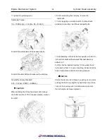
1. Remove the connecting rod caps.
✍
NOTICE
Mark the connecting rod caps to be able to reassemble
in the original position and direction.
2. Remove the piston and connecting rod assembly.
1) Using a ridge reamer, remove all the carbon from the
top of the cylinder.
2) Push the piston, connecting rod assembly and upper
bearing out of the cylinder block.
✍
NOTICE
• Keep the connecting rod and the cap with its bearings
together.
• Arrange the piston and connecting rod assemblies in
the correct order.
3. Remove the piston and connecting rod assembly.
Using a press machine, remove the piston pin from the
piston.
4. Remove the piston rings.
✍
NOTICE
Arrange the piston rings in its order, having an eye to
the 'Y' mark on the ring which tells you it is the upper
side.
5. Remove the flywheel and flywheel adapter
6. Remove the bedplate
7. Lift the crankshaft (A) out of the block, being careful
not to damage journals.
✍
NOTICE
Arrange the main bearings and thrust bearings in the
correct order
.
8. Remove the oil jet(A).
Summary of Contents for S220P
Page 3: ...Engine Mechanical System 2 General Information General Information Specifications ...
Page 4: ...Engine Mechanical System 3 General Information Specifications ...
Page 5: ...Engine Mechanical System 4 General Information Specifications ...
Page 10: ...Engine Mechanical System 9 Cooling System Special Service Tools ...
Page 11: ...Engine Mechanical System 10 Cooling System Special Service Tools ...
Page 18: ...Engine Mechanical System 17 Cooling System ...
Page 19: ...Engine Mechanical System 18 Cooling System Thermostat ...
Page 55: ...Engine Mechanical System 54 Lubrication System ...
Page 73: ...Engine Electrical System 72 General Information Troubleshooting Charging system ...
Page 74: ...Engine Electrical System 73 General Information Starting system Special service tools ...
Page 75: ...Engine Electrical System 74 Charging System Charging system Alternator ...
Page 80: ...Engine Electrical System 79 Starting System Components ...
Page 91: ...Fuel System 90 General Information Special Service Tools ...
Page 112: ...Fuel System 111 Diesel Control System EOI Engine Operating Indicator System Circuit Diagram 1 ...
Page 117: ...Fuel System 116 Diesel Control System Specification Circuit Diagram ...


