


Engine Electrical System 84 Preheating System
heating pin is pressed in. In the heating pin there are
the heating spiral and the sensor spiral, both are
connected in series and embedded in a ceramic mass.
Purpose
• Prior to engine starting : To make quickly available a
hot surface of approximately 850
℃
(1562
℉
), where the
air-fuel mixture evaporizes and ignites during the
compression stroke.
• While engine starting : To support the engine run-up.
• After engine starting : To improve the idle running
and to reduce the emissions of blue smoke, pollutants
and noise.
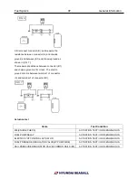
Inspection
The specified electrical data below are related to the
nominal voltage and to an ambient temperature of
22.5~23.5
℃
(72.5~74.3
℉
) on new glow plugs.
Current Consumption
-------------------------------------------------------------------
Initial current at 11V : less than 27.0A
Operating current after 5 sec : less than 9.0A
Operating current after 60 sec : less than 8.0A
-------------------------------------------------------------------
Cold Resistance
The measured values are valid for 4 minutes at nominal
voltage or for 10 minutes at 980
℃
(1796
℉
) pre-oxidized
glow plugs
------------------------------------------------------------------------
Glow plug resistance at 18~22
℃
(64.4~71.6
℉
) :
410±110mΩ
------------------------------------------------------------------------
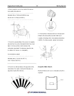
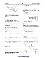
Removal
1. Remove the inlet lower and upper manifold
assembly.(Refer to Intake manifold in this Group)
2. Remove the glow plugs (A).
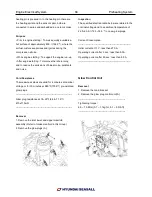
Glow Control Unit
Removal
1. Remove the main bracket.
2. Remove the glow plug control unit(A).
------------------------------------------------------------
Tightening torque
:
6.9 ~ 10.8Nm (0.7 ~ 1.1kgf.m, 5.1 ~ 8.0lb-ft)
------------------------------------------------------------
Summary of Contents for S220P
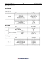
Page 3: ...Engine Mechanical System 2 General Information General Information Specifications ...
Page 4: ...Engine Mechanical System 3 General Information Specifications ...
Page 5: ...Engine Mechanical System 4 General Information Specifications ...
Page 10: ...Engine Mechanical System 9 Cooling System Special Service Tools ...
Page 11: ...Engine Mechanical System 10 Cooling System Special Service Tools ...
Page 18: ...Engine Mechanical System 17 Cooling System ...
Page 19: ...Engine Mechanical System 18 Cooling System Thermostat ...
Page 55: ...Engine Mechanical System 54 Lubrication System ...
Page 73: ...Engine Electrical System 72 General Information Troubleshooting Charging system ...
Page 74: ...Engine Electrical System 73 General Information Starting system Special service tools ...
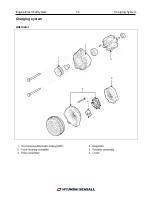
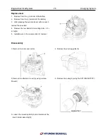
Page 75: ...Engine Electrical System 74 Charging System Charging system Alternator ...
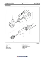
Page 80: ...Engine Electrical System 79 Starting System Components ...
Page 91: ...Fuel System 90 General Information Special Service Tools ...
Page 112: ...Fuel System 111 Diesel Control System EOI Engine Operating Indicator System Circuit Diagram 1 ...
Page 117: ...Fuel System 116 Diesel Control System Specification Circuit Diagram ...