


Fuel System 94 General Information
Connector Inspection Procedure
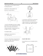
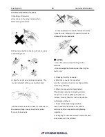
1. Handling of Connector
a. Never pull on the wiring harness when
disconnecting connectors.
b. When removing the connector with a lock, press
or pull locking lever.
c. Listen for a click when locking connectors. This
sound indicates that they are securely locked
d. When a tester is used to check for continuity, or
to measure voltage, always insert tester probe
from wire harness side
e. Check waterproof connector terminals from the
connector side. Waterproof connectors cannot be
accessed from harness side
✍
NOTICE
• Use a fine wire to prevent damage to the
terminal.
• Do not damage the terminal when inserting the
tester lead.
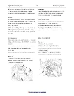
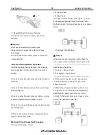
2. Checking Point for Connector
a. While the connector is connected:
Hold the connector, check connecting condition
and locking efficiency.
b. When the connector is disconnected:
Check missed terminal, crimped terminal or
broken core wire by slightly pulling the wire
harness. Visually check for rust, contamination,
deformation and bend.
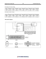
c. Check terminal tightening condition:
Insert a spare male terminal into a female
terminal, and then check terminal tightening
conditions.
d. Pull lightly on individual wires to ensure that each
wire is secured in the terminal.
Summary of Contents for S220P
Page 3: ...Engine Mechanical System 2 General Information General Information Specifications ...
Page 4: ...Engine Mechanical System 3 General Information Specifications ...
Page 5: ...Engine Mechanical System 4 General Information Specifications ...
Page 10: ...Engine Mechanical System 9 Cooling System Special Service Tools ...
Page 11: ...Engine Mechanical System 10 Cooling System Special Service Tools ...
Page 18: ...Engine Mechanical System 17 Cooling System ...
Page 19: ...Engine Mechanical System 18 Cooling System Thermostat ...
Page 55: ...Engine Mechanical System 54 Lubrication System ...
Page 73: ...Engine Electrical System 72 General Information Troubleshooting Charging system ...
Page 74: ...Engine Electrical System 73 General Information Starting system Special service tools ...
Page 75: ...Engine Electrical System 74 Charging System Charging system Alternator ...
Page 80: ...Engine Electrical System 79 Starting System Components ...
Page 91: ...Fuel System 90 General Information Special Service Tools ...
Page 112: ...Fuel System 111 Diesel Control System EOI Engine Operating Indicator System Circuit Diagram 1 ...
Page 117: ...Fuel System 116 Diesel Control System Specification Circuit Diagram ...