Engine Electrical System 83 Preheating System
Preheating System
General Description
Preheating on Diesel engine improves cold starting with
glow plug which heat combustion chamber. Preheating
before starting improves cold starting, preheating after
starting reduces to generate white smog. GCU(Glow
plug Control Unit) is installed on the upper side of
timing chain cover and is operated by 12V power
supply. GCU receives sensors data such as 1)engine
coolant temperature, 2)engine rpm, 3)fuel injection
amount from ECM via CAN communication in order to
control glow plug. GCU controls 1)glow plug operation
with PWM, 2)compensates voltage when low voltage
3)controls not to flow over current on glow plug 4)
retrieves DTC after diagnosing each glow plug
corresponding to engine condition.
ISS(Instant Starting System) operated by 4.4Voltage
which is slim and enhanced heating performance, is
newly adopted on S engine. GCU emerges battery
voltage to glow plug directly for 1~2sec. at IG key ON.
After that, GCU controls glow plug operating voltage
with PWM corresponding to engine condition. ISS glow
plug is increased to 1000
℃
within 2~3sec. so that
starting performance is reached as same level as
gasoline. In addition, it is realized that consumption of
electricity is optimized by PWM control.
Inspection
Conditions before inspection :
Battery voltage : 12V
Cooling water temperature : Below 30
℃
(86°F)
(Disconnect the water temperature sensor connector).
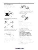
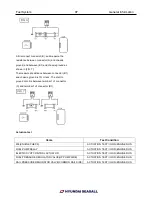
1. Connect voltmeter between glow plug plate and plug
body (ground).
2. Check indicated value on voltmeter with ignition
switch ON.
3. Check that preheat indication lamp lights for about 6
seconds and indicates battery voltage (about 9V or
over) for about 36 seconds immediately after ignition
switch is turned on. [At cooling water temperature20°C
(68.0°F)]
4. After checking 3, set ignition switch at START
position.
5. The system is normal if battery voltage (about 9V or
over) is generated for about 6 seconds during engine
cranking and after start operation. [at cooling water
temperature 20°C (68.0°F)]
6. When the voltage or continuity time is not normal,
check the terminal voltage in glow control unit, and
single parts.
Glow Plug
1. Check the continuity between the terminal and body
as illustrated. Replace if discontinuity or with large
resistance.
* Standard value
:
0.25Ω
2. Check for rust on glow plug plate.
3. Check glow plug for damage.
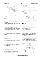
Structure
The glow plug mainly consists of a housing in which a
Summary of Contents for S220P
Page 3: ...Engine Mechanical System 2 General Information General Information Specifications ...
Page 4: ...Engine Mechanical System 3 General Information Specifications ...
Page 5: ...Engine Mechanical System 4 General Information Specifications ...
Page 10: ...Engine Mechanical System 9 Cooling System Special Service Tools ...
Page 11: ...Engine Mechanical System 10 Cooling System Special Service Tools ...
Page 18: ...Engine Mechanical System 17 Cooling System ...
Page 19: ...Engine Mechanical System 18 Cooling System Thermostat ...
Page 55: ...Engine Mechanical System 54 Lubrication System ...
Page 73: ...Engine Electrical System 72 General Information Troubleshooting Charging system ...
Page 74: ...Engine Electrical System 73 General Information Starting system Special service tools ...
Page 75: ...Engine Electrical System 74 Charging System Charging system Alternator ...
Page 80: ...Engine Electrical System 79 Starting System Components ...
Page 91: ...Fuel System 90 General Information Special Service Tools ...
Page 112: ...Fuel System 111 Diesel Control System EOI Engine Operating Indicator System Circuit Diagram 1 ...
Page 117: ...Fuel System 116 Diesel Control System Specification Circuit Diagram ...

