


Engine Mechanical System
34
Cylinder Head assembly
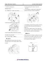
7. Tighten the glow plugs (A).
Tightening Torque:
7.8 ~ 10.8Nm (0.8 ~ 1.1kgf.m, 5.8 ~ 8.0lb-ft)
8. Install the water pipe and hose assembly(A).
9. Install the camshafts and measure the end play.
Camshaft end play Standard:
0.05 ~ 0.15mm (0.0020 ~ 0.0059in)
◉
CAUTION
When installing the RH exhaust camshaft, always
check the location of TDC (top dead center) mark on
the shaft.
10. After measuring the end play, remove the
camshafts.
11. After applying oil, install the HLA (hydraulic lash
adjuster) (A) and the cam follower assembly (B).
1) Until installing, HLA shall be held upright so that oil in
it should not spill and be assured that dust does not
adhere to it.
2) HLA shall be inserted tenderly to the cylinder head
not to spill oil from it. In case of spilling, air bent shall be
done in accordance with the air bent procedure.
✍
NOTICE
Stroke the HLA in oil 4~5 times by pushing its cap while
pushing the ball down slightly by hard steel wire. (Take
care not to severely push hard steel wire down since
the ball weighs just several grams.)
Summary of Contents for S220P
Page 3: ...Engine Mechanical System 2 General Information General Information Specifications ...
Page 4: ...Engine Mechanical System 3 General Information Specifications ...
Page 5: ...Engine Mechanical System 4 General Information Specifications ...
Page 10: ...Engine Mechanical System 9 Cooling System Special Service Tools ...
Page 11: ...Engine Mechanical System 10 Cooling System Special Service Tools ...
Page 18: ...Engine Mechanical System 17 Cooling System ...
Page 19: ...Engine Mechanical System 18 Cooling System Thermostat ...
Page 55: ...Engine Mechanical System 54 Lubrication System ...
Page 73: ...Engine Electrical System 72 General Information Troubleshooting Charging system ...
Page 74: ...Engine Electrical System 73 General Information Starting system Special service tools ...
Page 75: ...Engine Electrical System 74 Charging System Charging system Alternator ...
Page 80: ...Engine Electrical System 79 Starting System Components ...
Page 91: ...Fuel System 90 General Information Special Service Tools ...
Page 112: ...Fuel System 111 Diesel Control System EOI Engine Operating Indicator System Circuit Diagram 1 ...
Page 117: ...Fuel System 116 Diesel Control System Specification Circuit Diagram ...