Engine Mechanical System
42
Cylinder block
2. Check the connecting rods.
1) When reinstalling, make sure that cylinder numbers
put on the connecting rod and cap at disassembly
match. When a new connecting rod is installed, make
sure that the notches for holding the bearing in place
are on the same side.
2) Replace the connecting rod if it is damaged on the
thrust faces at either end. Also if step wear or a
severely rough surface of the inside diameter of the
small end is apparent, the rod must be replaced as
well.
3) Using a connecting rod aligning tool, check the rod
for bend and twist. If the measured value is close to
the repair limit, correct the rod by a press. Any
connecting rod that has been severely bent or
distorted should be replaced.
Crankshaft
1. Check the crankshaft bearing oil clearance.
1) To check main bearing-to-journal oil clearance,
remove the bed plate and lower bearings.
2) Clean each main journal and lower bearing with a
clean shop towel.
3) Place one strip of plastic gauge across each main
journal.
4) Reinstall the lower bearings and bed plate, and
then tighten the bolts.
✍
NOTICE
• Reinstall the lower bearings and bed plate, and then
tighten the bolts.
• If the bed plate bolts are damaged or deformed,
replace them with new ones.
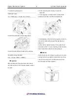
5) Tighten the No.18, 20, 21 bolts in its number order
(18
→20→21) with the specified torque.
Tightening Torque:
29.4 ~ 33.3Nm (3.0 ~ 3.4kgf.m, 21.7 ~ 24.6lb-ft)
6) Tighten the No.1~16 bolts in two steps with the
specified torque and angle below.
Tightening Torque:
61.8 ~ 65.7Nm (6.3 ~ 6.7kgf.m, 45.6 ~ 48.5lb-ft) – 1st
step 120° ~ 124° - 2nd step
7) Loosen the bolts No. 18, 20 and 21.
8) Tighten the No.17~25 bolts with the specified
torque below.
Tightening Torque:
29.4 ~ 33.3Nm (3.0 ~ 3.4kgf.m, 21.7 ~ 24.6lb-ft) – 1st
step
✍
NOTICE
Do not rotate the crankshaft.
9) Remove the bed plate and lower bearing again,
and measure the widest part of the plastic gauge.
Summary of Contents for S220P
Page 3: ...Engine Mechanical System 2 General Information General Information Specifications ...
Page 4: ...Engine Mechanical System 3 General Information Specifications ...
Page 5: ...Engine Mechanical System 4 General Information Specifications ...
Page 10: ...Engine Mechanical System 9 Cooling System Special Service Tools ...
Page 11: ...Engine Mechanical System 10 Cooling System Special Service Tools ...
Page 18: ...Engine Mechanical System 17 Cooling System ...
Page 19: ...Engine Mechanical System 18 Cooling System Thermostat ...
Page 55: ...Engine Mechanical System 54 Lubrication System ...
Page 73: ...Engine Electrical System 72 General Information Troubleshooting Charging system ...
Page 74: ...Engine Electrical System 73 General Information Starting system Special service tools ...
Page 75: ...Engine Electrical System 74 Charging System Charging system Alternator ...
Page 80: ...Engine Electrical System 79 Starting System Components ...
Page 91: ...Fuel System 90 General Information Special Service Tools ...
Page 112: ...Fuel System 111 Diesel Control System EOI Engine Operating Indicator System Circuit Diagram 1 ...
Page 117: ...Fuel System 116 Diesel Control System Specification Circuit Diagram ...


