


Digital Communications Interfaces ________________________________________________________
RF-MCGARDPRO
Hubbell Power Systems, Inc.
–
RFL™
Products
July 1, 2022
©2022 Hubbell Incorporated
7-33
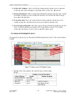
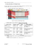
3.
Data Rate
: If the module carries one data channel or timeslot, this is 64 kbps. If a
module carries more than one, channel framing is enabled, so the data rate is (# of data
ch 1) * (64 kbps). This is because the framing function adds one timeslot’s
worth of data.
The data rate is multiples of 64, up to 832 kbps. If module is Disabled or Forced Disabled,
field = “0”.
4.
Timing
: This value tells the user the timing setting of the interface.
Range: Internal (Bus n Master), Internal (Bus n Slave), Loop (Bus n Master)
If module is Disabled or Forced Disabled, field = “N/A”
5.
Channel Framing
: This value tells the user the framing setting of the interface.
The status is Enabled or Disabled.
If module is Disabled or Forced Disabled, field = “N/A”.
6.
Channel Frame Lock
: This value tells the user the status of the frame lock of the
interface.
The status is
Yes or No.
If module is Disabled or Forced Disabled, field = “N/A”. If
channel framing is disable, value is N/A.
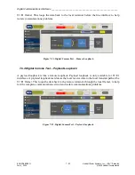
7.
Tx Activity
:
This is a status from the module of the Tx activity.
When healthy the value of this field is “OK”, in alarm the field reads “No Tx Activity”.
8.
Rx Activity
: This is a status from the module of Rx activity.
When healthy the value of this field is “OK”, in alarm the field reads “No Rx Activity”.
9.
Remote Alarm
: This is a status from the module if there is a remote alarm.
If there are no remote alarms the field reads “None”. When there is a remote alarm the
field reads “Active”. A remote alarm is sometimes called a yellow alarm and indicates a
receive problem at the remote end.
10.
PLL Lock
: This indicates interface timing lock.
When not “Locked” the field reads “No”.
11.
Loopback
: This is a status from the module for loopback.
This field will never be in the ‘green’ state because it is disabled if Loopback is
Inactive.
12.
Tx/Rx Clock Polarity
: This value tells the user the Tx/Rx Clock Polarity setting of the
interface.
If module is Disabled or Forced Disabled, field = “N/A”
13.
Tx/Rx Data Polarity
: This value tells the user the Tx/Rx Data Polarity setting of the
interface.
If module is Disabled or Forced Disabled, field = “N/A”