


Digital Communications Interfaces ________________________________________________________
RF-MCGARDPRO
Hubbell Power Systems, Inc.
–
RFL™
Products
July 1, 2022
©2022 Hubbell Incorporated
7-13
7.3
Digital Communications Timeslot configuration
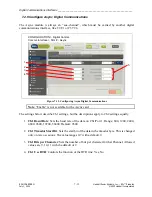
This page configures the GARD Internal Comms Bus. There are two buses available, Comms
Bus 1 (“Bus 1”) and Comms Bus 2 (“Bus 2”). Each Bus has its own tab. Within a bus, there are
12 “timeslots” which run at 64 kbps each. A timeslot must have a function / interface
combination to have valid programming. But it can also be empty.
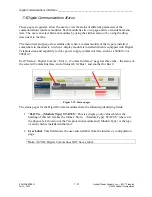
Each comms bus requires a master time source, or "Bus Master". The bus master provides the
synchronous timing for the bus. The bus master timing can be either "internal" or "loop".
Internal timing is derived from a local crystal oscillator. Loop timing is recovered from the
received communications signal. There are several rules and programming requirements
specific to handling how the master is assigned and programmed.
Note
: Bus timing is independent of the system real-time clock, used for synchronizing
Sequence of Events.
Multiple communications interfaces can be assigned to a bus. There can only be one bus master
interface. Additional interfaces are considered bus slaves. Slave interfaces are always timed
from the bus and as a result, the bus master itself. As a result, care should be taken when
establishing communications channels between two slave interfaces as they may have different
timing sources.
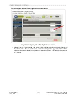
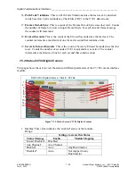
Figure 7-13. Digital Comms Timeslot Configuration screen


