


Power Line Carrier ____________________________________________________________________
RF-MCGARDPRO
Hubbell Power Systems, Inc.
–
RFL™
Products
July 1, 2022
©2022 Hubbell Incorporated
5-64
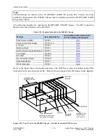
5.6.5 Line Board
The HPS/RFL 9508 Line Board serves as the connection point between the HPS/RFL 9508 RF
Chassis and the Line Coupling equipment. Because it contains no active components, the Line
Board does not require any dc input voltage.
100
P
200
P
300
P
410
P
.001UF
.002UF
12
.1
1
/2
W
1
2
2
.5
W
1
2
2
.5
W
5
0
2
.5
W
5
0
5
W
.003
UF
.0041
UF
.01
UF
56UH
9.5A
100UH
9.5A
180UH
9.5A
12
.1
1
/2
W
12
.1
1
/2
W
8-18UH
10UH
9.5A
18UH
9.5A
33UH
9.5A
55869
55869
55689
55688
FU
S
E
2
A
250
V
FU
S
E
H
O
L
D
E
R
32882
FUSEHOLDER
32882
FUSE 2A 250V
121
47
.5
4733
A
4733
A
43
.2
A
R
R
E
S
T
O
R
92627
99134
180
UH
92627
A
R
R
E
S
T
O
R
P
A
R
T
N
U
M
B
E
R
S
E
R
IA
L
N
U
M
B
E
R
130
/150
130/150
G
TP8
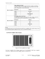
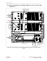
Figure 5-41. Line Board
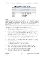
Theory of Operation
The RF Line board connects the HPS/RFL 9508 to the line coupling equipment. It contains two
hybrid transformers, a receive attenuator, a complex balance network, two impedance matching
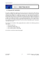
transformers, and two surge arrestors. A block diagram of the Line Board appears below.
Transmit Input 1
From Power Amp 1
RF From/To
Line Coupling
Equipment
Hybrid
Transformers
Impedance
Matching
Transformers
Receive
Attenuator
Surge
Arrestors
IN J11
OUT
Receive
Output to
RX Filter
Transmit Input 2
From Power Amp 2
(when used)
Complex
Balance
Network
Figure 5-42. RFL9508 Line Board, Block Diagram


