Digital Communications Interfaces ________________________________________________________
RF-MCGARDPRO
Hubbell Power Systems, Inc.
–
RFL™
Products
July 1, 2022
©2022 Hubbell Incorporated
7-24
Configuration process
Note
: For the initial configuration process you must connect locally to G1, G2 and G3.
The IP addresses must not conflict with any address on the IP network.
1.
Decide which units in the system will be primary (Service Channel A) and which will be
secondary (Service Channel B). Each service channel must have one primary and one
secondary connection.
2.
Connect locally to the unit to be configured.
3.
Navigate to “ADVANCED > Service Channels” and fill out the Service Channel address,
Netmask and remote IP address.
a)
Enter Service Channel IP for Remote Unit. This is the IP address used at the Local
end used to connect with the Remote end over the service channel. This IP address
must not conflict with any address on the IP network.
b)
Enter the Remote System Netmask. The Netmask must match with the network mask
of the rear port at the Remote end.
c)
Enter the Remote System rear IP address. This address must match with the rear port
IP address at the Remote end.
Allocate Timeslots for the Service Channels
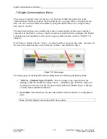
Service Channels must be allocated Timeslots on the comms Bus.
1.
Navigate to Configuration > Digital Comms and select a Timeslots Bus tab.
2.
In an unused Timeslot for the Function, select the Select the Service Channel A or B.
3.
In the Interface, select the “Slot – Card” to use for the Service Channel


