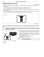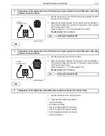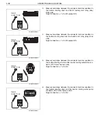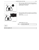
HYBRID/TROUBLE SHOOTING
3–50
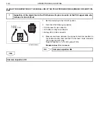
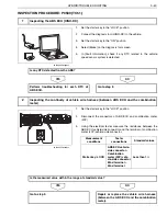
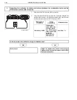
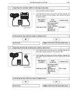
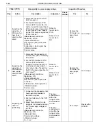
7
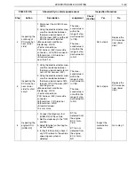
Inspecting the
PCU wire har-
ness signal
line for short
circuit
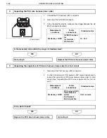
1. Set the starter key to the
"LOCK" position.
2. For the 18th terminal of PCU
harness (24P) lower-side con-
nector, inspect the signal line of
PCU wire harness (lower side)
for short circuit. (See "Inspect-
ing the PCU harness signal line
for short circuit.")
<Measurement conditions>
Starter key: LOCK
<Tester connections>
PCU harness (24P) lower-side
connector
18th terminal
–
Each signal line
<Standard values>
10 k
or more
Defect is
found: Go to
YES.
Defect is not
found: Go to
NO.
Replace the
PCU wire har-
ness (lower
side).
Go to step 8.
8
Reproduction
check [HINO-
DX]
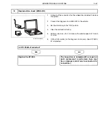
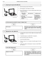
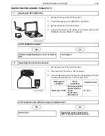
1. Connect all the connectors that
have been disconnected to
restore the system.
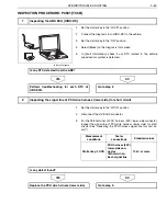
2. Connect the diagnosis tool
(HINO-DX) to the vehicle.
3. Set the starter key to the "ON"
position.
4. Clear the malfunction history.
5. Perform a test run. (For 1 min-
utes at the vehicle speed of 10
km/h or more)
6. In [Fault Information] on the
diagnosis tool screen, check if
P0500-51 is detected.
DTC P0500-
51 is detected:
Go to
YES.DTC
P0500-51 is
not detected:
Go to NO.
Replace the
HV ECU.
The inspec-
tion is com-
pleted.(If no
repair or parts
replacement is
performed,
there may be
an improper
contact due to
connector dis-
connection.)
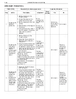
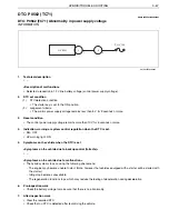
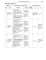
P0500 (TC51)
Abnormality in vehicle speed sensor
Inspection Procedure
Step
Action
Description
Judgement
Check
(Yes/No)
Yes
No

