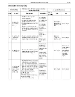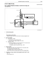
HYBRID/TROUBLE SHOOTING
3–317
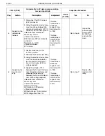
1.
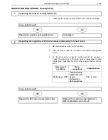
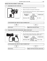
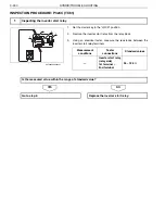
Set the starter key to the "LOCK" position.
2.
Disconnect the HV ECU1 connector.
3.
Using the electrical tester, measure the resistance between the
inverter cooling pump connector and the HV ECU1 connector ter-
minal.
NO
YES
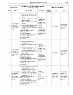
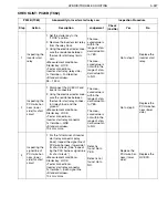
1.
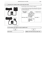
For the 2nd terminal of inverter cooling pump connector, inspect
the signal line of PCU wire harness (lower side) for short circuit.
(See "Inspecting the PCU harness signal line for short circuit.")
NO
YES
8
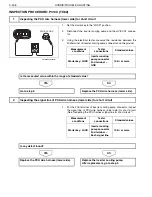
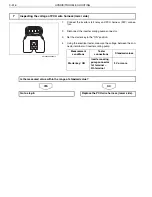
Inspecting the continuity of PCU wire harness (lower side)
SHTS03ZZZ0300215
Measurement
conditions
Tester
connections
Standard values
Starter key: LOCK
Inverter cooling
pump connector
–
HV ECU1 connec-
tor
2nd terminal
–
26th terminal
Less than 1
Is the measured value within the range of standard value?
Go to step 9.
Replace the PCU wire harness (lower side).
9
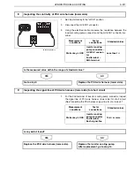
Inspecting the signal line of PCU wire harness (lower side) for short circuit
Measurement
conditions
Tester
connections
Standard values
Starter key: LOCK
Inverter cooling
pump connector
2nd terminal
–
Each signal line
10 k
or more
Is any defect found?
Replace the PCU wire harness (lower side).
Replace the inverter cooling pump.
After replacement, go to step 10.

