HYBRID/TROUBLE SHOOTING
3–669
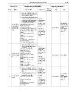
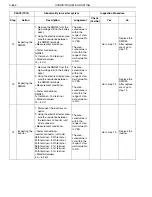
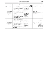
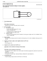
CHECKLIST: P0A78 (TC15)
P0A78 (TC15)
Abnormality in inverter system
Inspection Procedure
Step
Action
Description
Judgement
Check
(Yes/No)
Yes
No
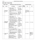
1
Inspecting the
three-phase
cable 1
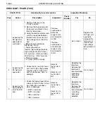
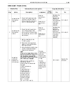
1. Check the three-phase cable
connector (inverter-side) for
failing connection (looseness,
wear, or melting damage).
Defect is
found: Go to
YES.
Defect is not
found: Go to
NO.
Retighten the
terminals.
Replace the
terminals if
abnormal wear
or melting
damage is
detected.
Go to step 2.
2
Inspecting the
three-phase
cable 2
1. Check the ring tongue termi-
nals of three-phase cable
(motor side) for failing connec-
tion (looseness, wear, or melt-
ing damage).
Defect is
found: Go to
YES.
Defect is not
found: Go to
NO.
Retighten the
terminals.
Replace the
terminals if
abnormal wear
or melting
damage is
detected.
Go to step 3.
3
Inspecting
resistance
between HV
motor phases
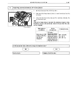
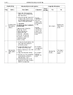
1. Set the starter key to the
"LOCK" position.
2. Disconnect the three-phase
cable (U, V, and W terminals)
from the HV motor.
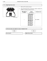
3. Using the electrical tester, mea-
sure the resistance between
the HV motor terminals.
HINT
If the motor temperature is too
high, the resistance largely var-
ies. Therefore, measure the
resistance at least 8 hours after
the vehicle has stopped.
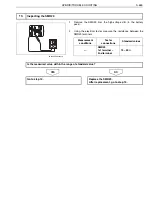
<Measurement conditions>
Starter key: LOCK
(8 hours after the vehicle has
stopped)
<Tester connections>
HV motor
U-phase terminal
–
V-phase terminal
U-phase terminal
–
W-phase terminal
V-phase terminal
–
W-phase terminal
<Standard values>
38.2
–
40.5 M
(15
–
30
C {59
–
86
F})
The mea-
sured value is
within the
range of stan-
dard value: Go
to YES.
The mea-
sured value is
not within the
range of stan-
dard value: Go
to NO.
Go to step 4.
Replace the
HV motor.

