HYBRID/TROUBLE SHOOTING
3–719
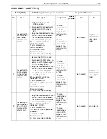
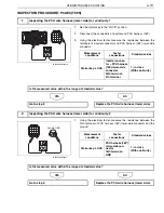
INSPECTION PROCEDURE: P0AE6 (TC1D)
1.
Set the starter key to the "LOCK" position.
2.
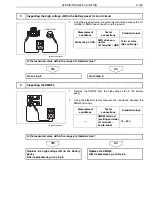
Disconnect the connectors of inverter and PCU harness (16P).
3.
Using the electrical tester, measure the resistance between the
38th terminal of inverter connector and the ground.
NO
YES
1.
Remove the PCU top cover.
2.
Disconnect the SMR drive connector from the high-voltage J/B (in
the battery pack).
3.
Using the electrical tester, measure the resistance between the
2nd terminal of PCU harness (16P) upper-side connector and the
ground.
NO
YES
1
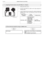
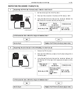
Inspecting the PCU wire harness (lower side) for short circuit
Vehicle GND
SHTS03ZZZ0300476
Measurement
conditions
Tester
connections
Standard values
Starter key: LOCK
Inverter connector
38th terminal
–
GND
10 k
or more
(No continuity)
Is the measured value within the range of standard value?
Go to step 2.
Replace the PCU wire harness (lower side).
2
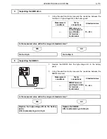
Inspecting the wire harness in the HV battery for short circuit
Vehicle GND
SHTS03ZZZ0300477
Measurement
conditions
Tester
connections
Standard values
Starter key: LOCK
PCU harness (16P)
upper-side con-
nector
2nd terminal
–
GND
10 k
or more
(No continuity)
Is the measured value within the range of standard value?
Go to step 3.
Replace the PCU wire harness (upper side).

