HYBRID/TROUBLE SHOOTING
3–591
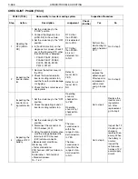
16
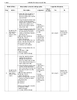
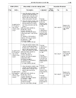
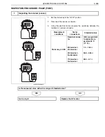
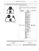
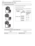
Inspecting the
PCU wire har-
ness (lower
side) for conti-
nuity
1. Set the starter key to the
"LOCK" position.
2. Disconnect the connectors of
inverter cooling pump and HV
ECU2.
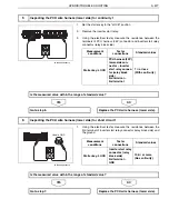
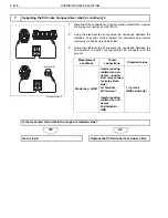
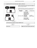
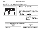
3. Using the electrical tester, mea-
sure the resistance between
the terminals of inverter cooling
pump connector and HV ECU2
connector.
<Measurement conditions>
Starter key: LOCK
<Tester connections>
Inverter cooling pump connector
– HV ECU2 connector
3rd terminal – 43rd terminal
<Standard values>
1
or less (With continuity)
The mea-
sured value is
within the
range of stan-
dard value: Go
to YES.
The mea-
sured value is
not within the
range of stan-
dard value: Go
to NO.
Go to step 17.
Replace the
PCU wire har-
ness (lower
side).
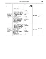
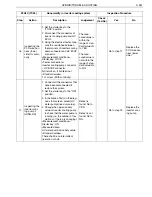
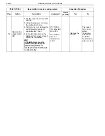
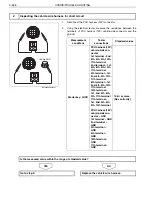
17
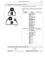
Inspecting the
inverter cool-
ing pump 2
[HINO-DX]
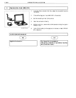
1. Connect all the connectors that
have been disconnected to
restore the system.
2. Set the starter key to the "ON"
position.
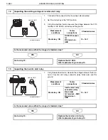
3. In [Activation Test] on the diag-
nosis tool screen, select [HV
water pump drive duty value].
4. Change the operation duty
value of inverter cooling pump
to check that the water pump is
running (i.e. the number of rev-
olutions of the fan is changing).
<Measurement conditions>
Starter key: ON
<Measured item>
HV water pump drive duty value
<Standard values>
There shall be no intermittent
operation or halt.
Defect is
found: Go to
YES.
Defect is not
found: Go to
NO.
Go to step 18.
Replace the
inverter cool-
ing pump.
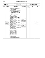
P0A3C (TC34)
Abnormality in inverter cooling system
Inspection Procedure
Step
Action
Description
Judgement
Check
(Yes/No)
Yes
No

