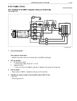
HYBRID/TROUBLE SHOOTING
3–731
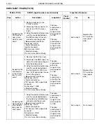
4
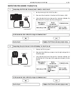
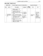
Inspecting the
SMR drive
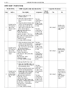
1. Using the electrical tester, mea-
sure the resistance between
the terminals of high-voltage J/
B (in the battery pack).
<Measurement conditions>
—
<Tester connections>
SMR drive connector
(high-voltage J/B side)
3rd terminal
–
2nd terminal
<Standard values>
19
–
50
The mea-
sured value is
within the
range of stan-
dard value: Go
to YES.
The mea-
sured value is
not within the
range of stan-
dard value: Go
to NO.
Go to step 6.
Go to step 5.
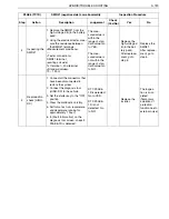
5
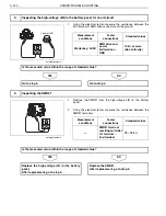
Inspecting the
SMR#1
1. Remove the SMR#1 from the
high-voltage J/B (in the battery
pack).
2. Using the electrical tester, mea-
sure the resistance between
the SMR#1 terminals.
<Measurement conditions>
—
<Tester connections>
SMR#1 terminal
(exciting coil side)
1st terminal
–
2nd terminal
<Standard values>
19
–
50
The mea-
sured value is
within the
range of stan-
dard value: Go
to YES.
The mea-
sured value is
not within the
range of stan-
dard value: Go
to NO.
Replace the
high-voltage J/
B (in the bat-
tery pack).
After replace-
ment, go to
step 6.
Replace the
SMR#1.
After replace-
ment, go to
step 6.
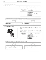
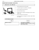
6
Reproduction
check [HINO-
DX]
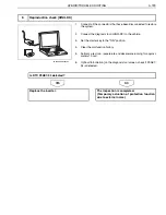
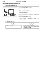
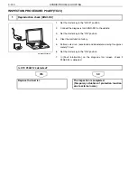
1. Connect all the connectors that
have been disconnected to
restore the system.
2. Connect the diagnosis tool
(HINO-DX) to the vehicle.
3. Set the starter key to the "ON"
position.
4. Clear the malfunction history.
5. Perform a test run. (accelerate
and decelerate running for
approximately 1 hour).
6. In [Fault Information] on the
diagnosis tool screen, check if
P0AE7-94 is detected.
DTC P0AE7-
94 is detected:
Go to YES.
DTC P0AE7-
94 is not
detected: Go
to NO.
Replace the
inverter.
The inspec-
tion is com-
pleted.
(Temporary
actuation of
protection
function due to
external noise)
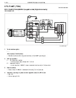
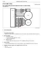
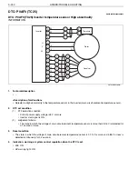
P0AE7 (TC94)
SMR#1 (negative side) High abnormality
Inspection Procedure
Step
Action
Description
Judgement
Check
(Yes/No)
Yes
No

